MUL-E03020101
This article is not made by me. This is done for archiving the mod in my personal store. The website is set to go down. Original is in DE translated using google.
| Author | Website |
|---|---|
| Erste Schritte | http://deutschermanfred.de/ |
Housing
So you've decided to mod a Playstation 1 ? As a result, you want a full-fledged high-end CD player to complement your system?
GREAT
This guide is about buying the right PS1. Furthermore, to completely disassemble the case without causing damage such as stripped screws, broken brackets, etc. develop.
Let's start with lots of fun....
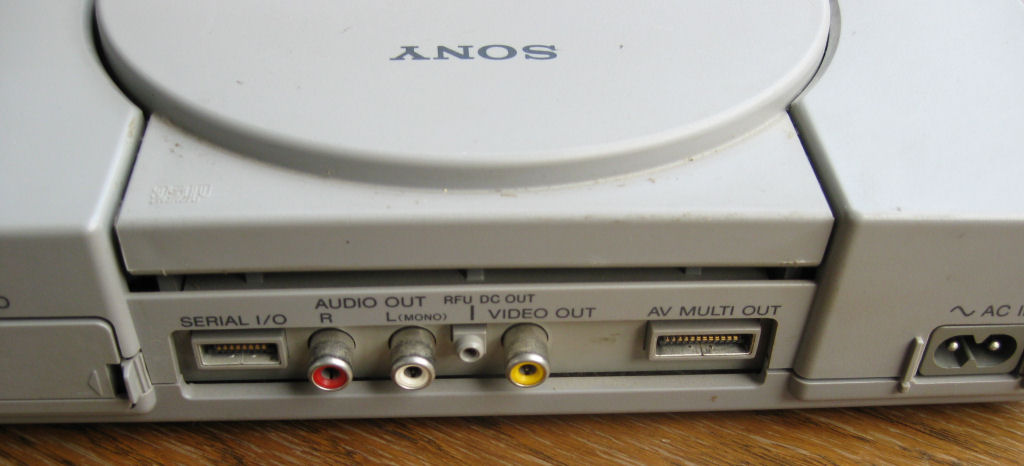
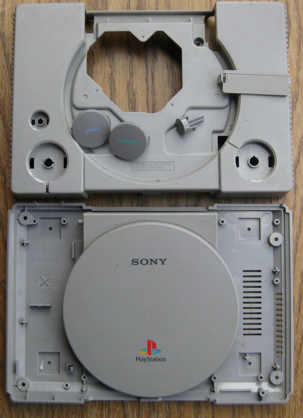
But beware, there are people everywhere who post photos of a SCPH-100 2 and then deliver a device from the 5000 or 7000 series. As the?? Quite simply, you take the "POWER and OPEN" control buttons of a Playstation 1 SCPH-1002 and then put them in a device of the 5000 series, for example. Any further description is then often missing. I fell for it once but never again.
This means: Only the SCPH-1002 has the buttons “POWER and OPEN” as shown in the photo. All other models have symbols on the keys, at least I'm not aware of anything else.
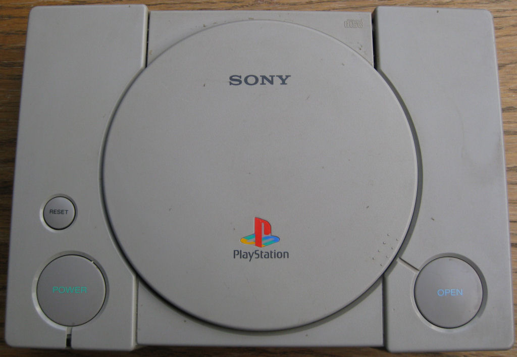
So here's my tip!
Make sure that the item description says SCPH-1002, or that there is a photo of the back. Otherwise write to the seller and ask.
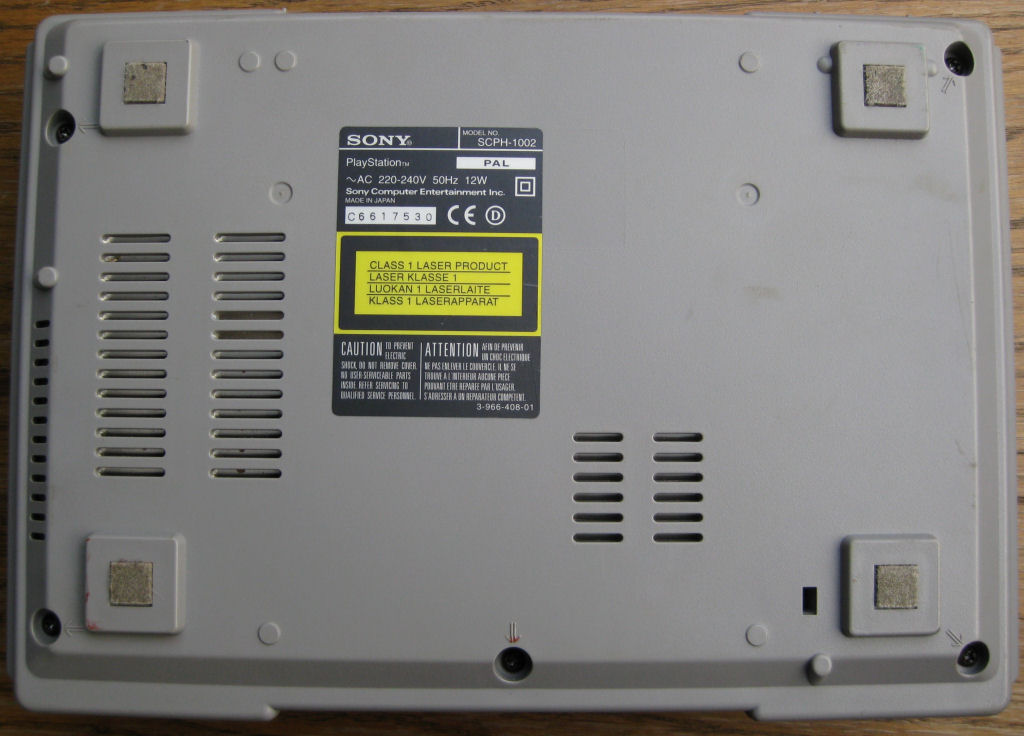
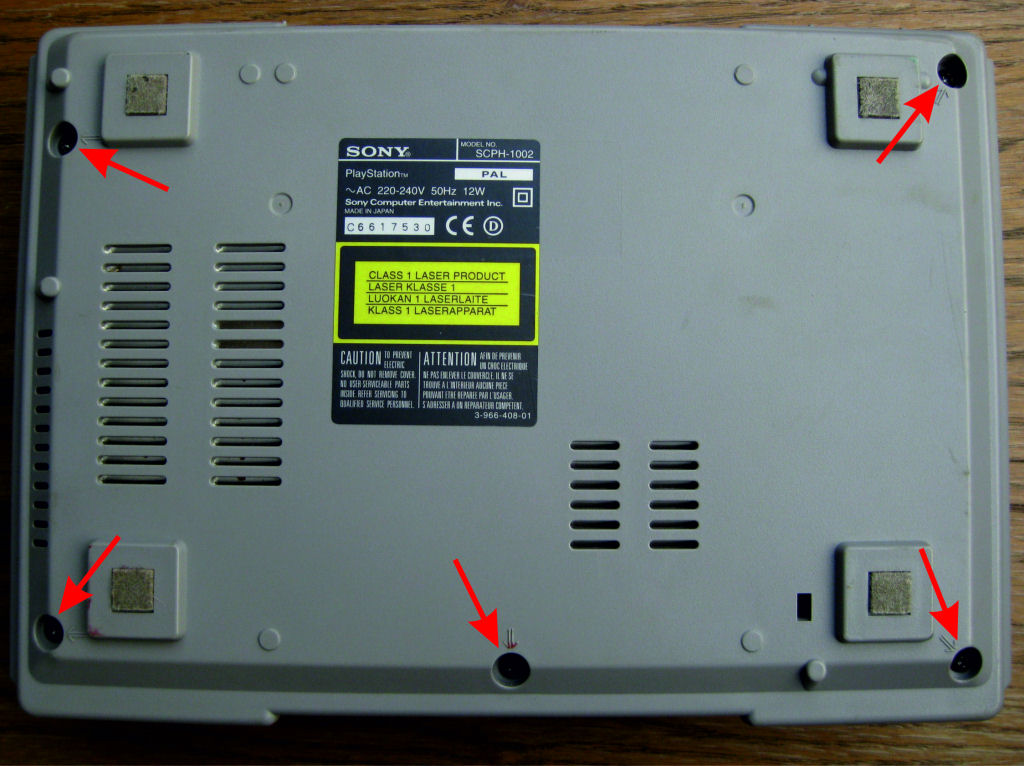
You often get devices that are very dirty, as can be seen here, but that doesn't detract from the matter.
Please remove all 5 screws here. The upper part can then be easily removed.
Please don't complain like, that's white. I've been asked several times to post a step-by-step guide.
Even the most inexperienced should understand it. And that's just as well.....
The sticker is best removed by heating it with a hair dryer. Then there are no sticky residues that are difficult to remove. Likewise the felt feet.
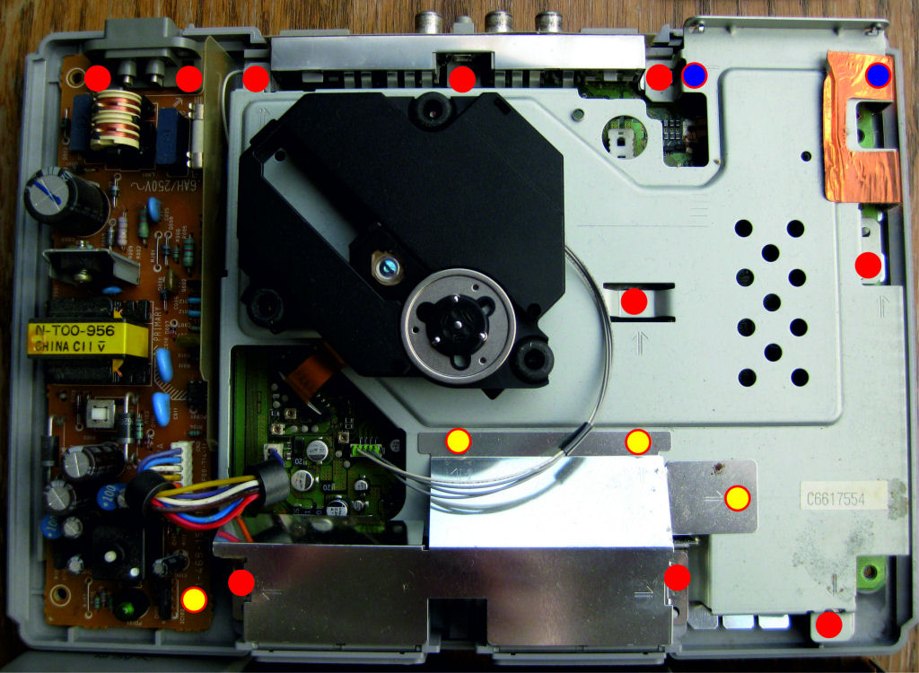
That's how it goes. Please unscrew all the screws and simply peel off the copper foil.
red/yellow = short screws
red = long screws
red / blue = long screws
The red/blue sit under the chassis. They can only be unscrewed when the sheet metal chassis is lifted off. But first remove the laser unit (next picture)
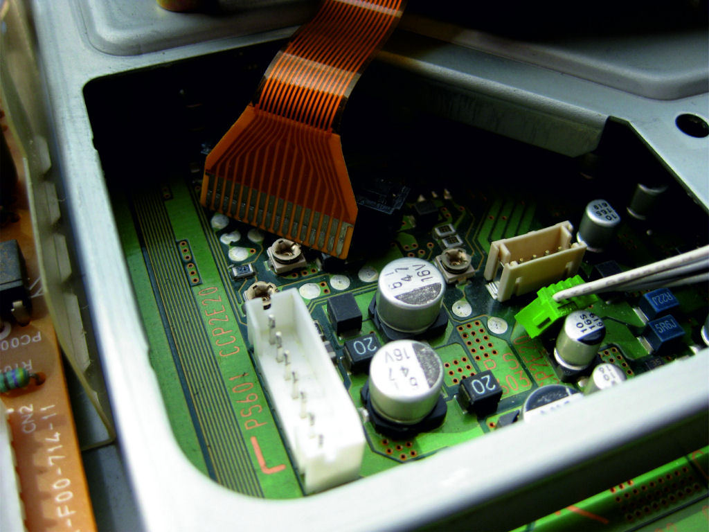
Simply unplug the power supply from the motherboard
The lines from NT to the board are removed, red arrows.
White arrow, simply pull up the connector from the drive.
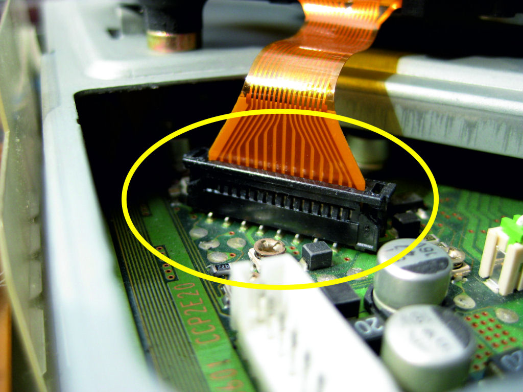
Unlock the socket for the flex board (yellow arrows). It is best to use a small screwdriver and carefully lever the lock up by about 1mm in the direction of the arrow. But really very careful, because the retaining lugs break off super easily.
If it does happen, the base has to be replaced, which can be difficult for the inexperienced. But I have advice for that too. Then a socket from a PS1 of the 7000/9000 series is simply soldered in.
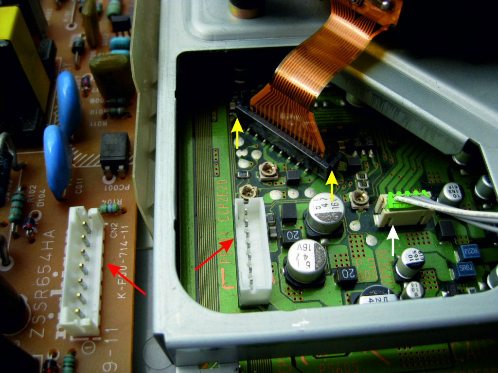
When the lock is open, just like in the picture, the flex circuit board can be easily removed.
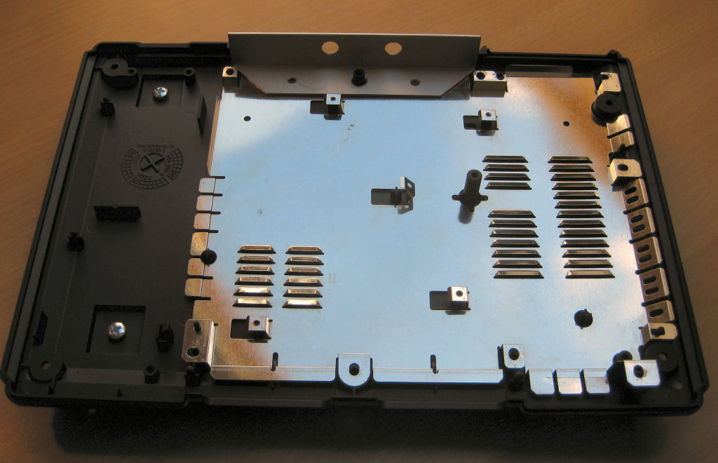
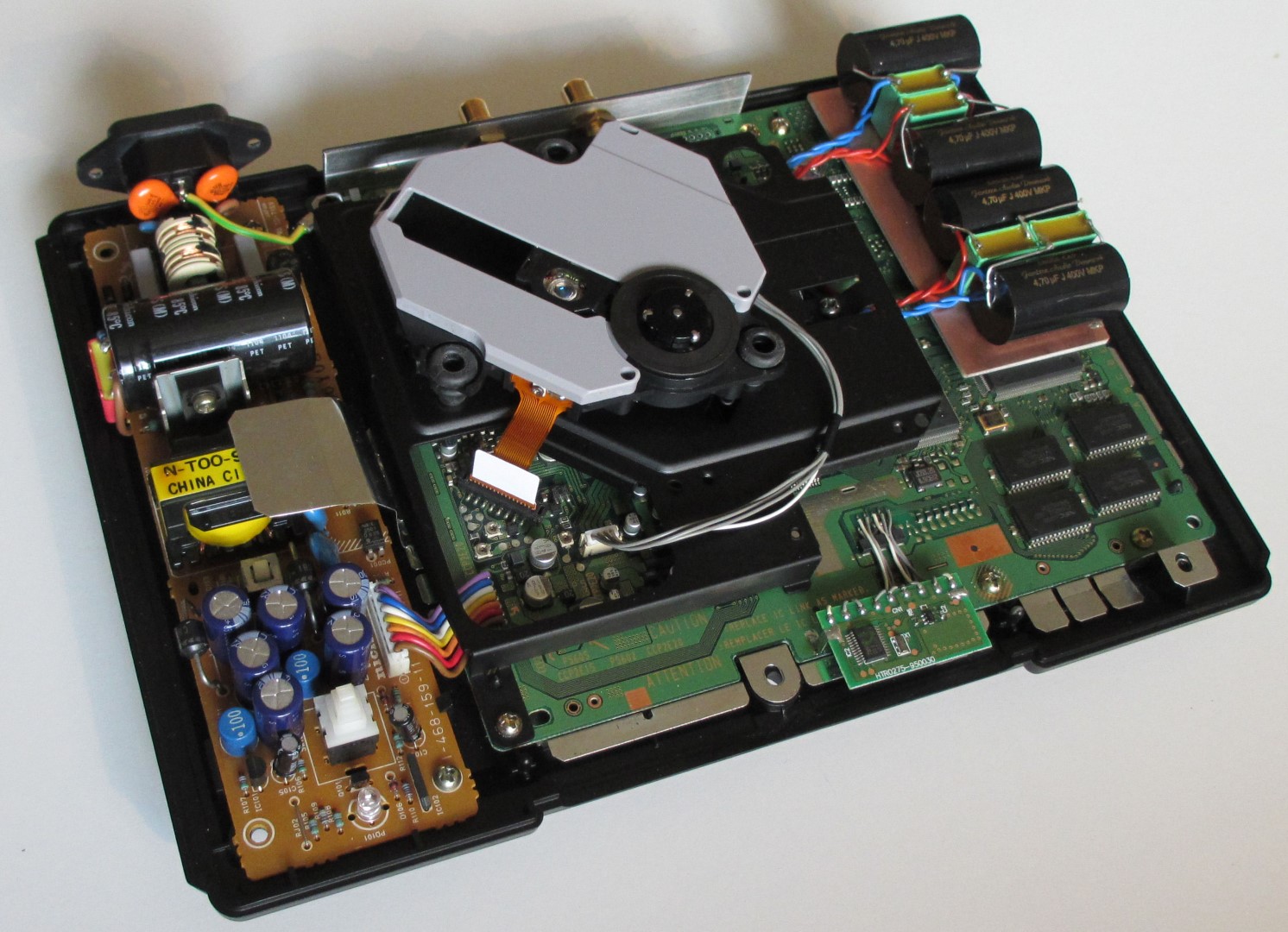
So, now the laser unit, the power pack and the sheet metal chassis can be removed.
When everything is in front of you as shown, you're almost done!
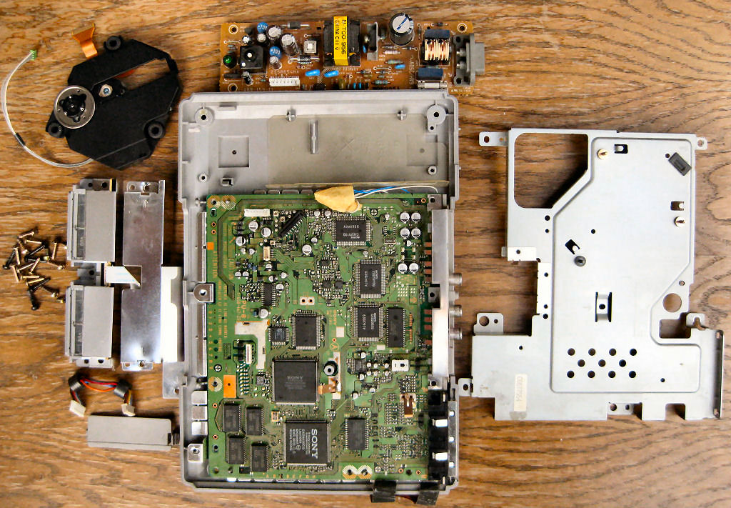
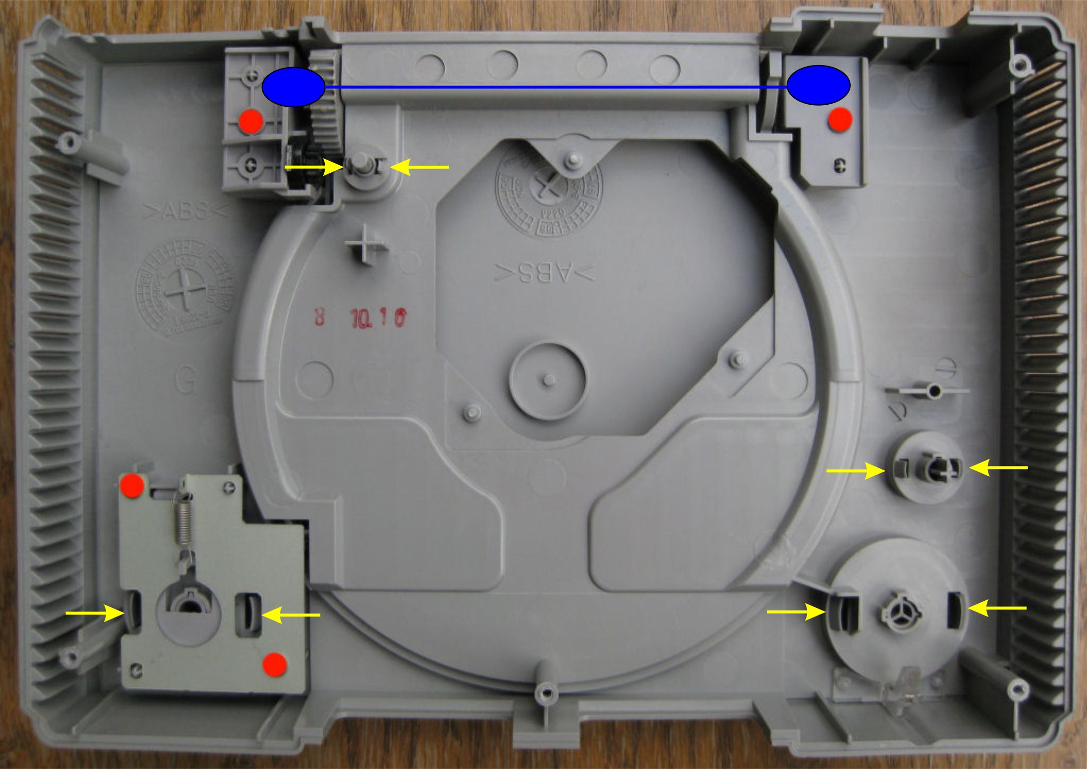
Simply remove the four screws marked in red and remove the loosened parts.
Then press the yellow retaining tabs of the operating buttons and the lid switch in the direction of the arrow, push to the surface and remove.
The parts marked in blue are the lid hinges.
My tip: put the lid mechanism back together several times so that you don't cause any scratches later when everything is painted. At first it is a little fiddling to put the spring back in place without damaging the paintwork. This will give you a little practice and make it easier to do. I always put the lid on first, then the bracket and finally the lid mechanism with the spring. Like I said, practice a few times.
If you have any questions up to this point, please feel free to contact me.
I am happy to help....
The simplest thing is probably the processing of the housing.
It is completely disassembled and lightly sanded with 600 grit wet sandpaper. Likewise the control buttons and the lid. Deep scratches are closed with a fine spatula and sanded.
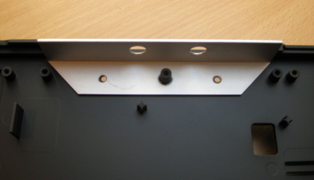
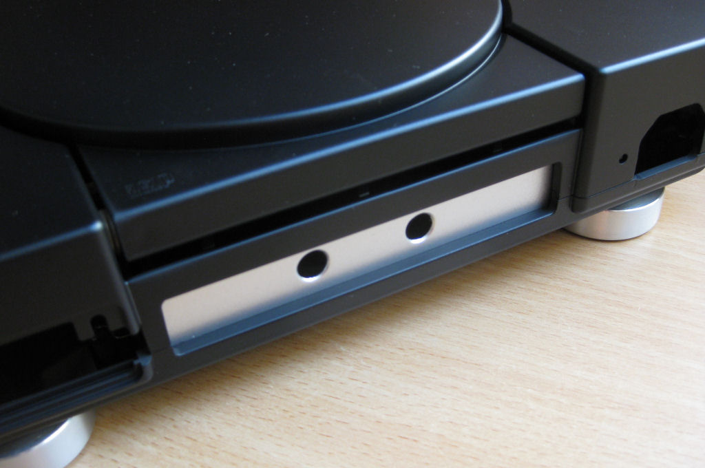
An aluminum angle is used for the rear bulkhead, which can be bought in any hardware store. This is definitely the most stable and safest solution. Nothing wobbles, nothing breaks.
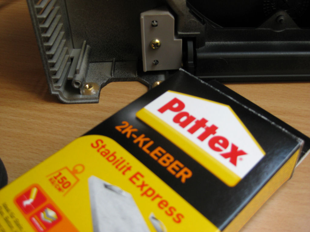
The nuts for the IEC socket are simply attached with Pattex Stabilit Express. Bombproof!
The paint consists of 2 coats of primer from AutoK. The can costs around €7.00 in a hardware store. The paint finish consists of 3 layers of paint, also from AutoK. The can in the hardware store costs about €7.00
However, both are also available under the name Sprayla, from exactly the same manufacturer, on EBAY and do not even cost €3.00. That's a great saving, isn't it? Of course, this is just my own application variant and corresponds to this description. The type of painting is of course up to you and your creativity.

Power supply
If you need a decent power supply for your PS, you should use a 5-pin one. The advantage of these power supplies is the low heat development, even in the unmodified state. Of course, the power pack with a 7-pin connection can also be used without any problems. It only gets slightly warmer.
If you don't own one, you can bid for one on EBAY for a small fee. Simply bid on a PS1 of the 7000 or 9000 series, which are offered in bulk.
The information given here is based on information collected from the Internet.
Have lots of fun with it!
The 5PIN power supply is modified in this manual! The 7PIN power supply differs only slightly and can also be modified according to these instructions. Just look at the layout!
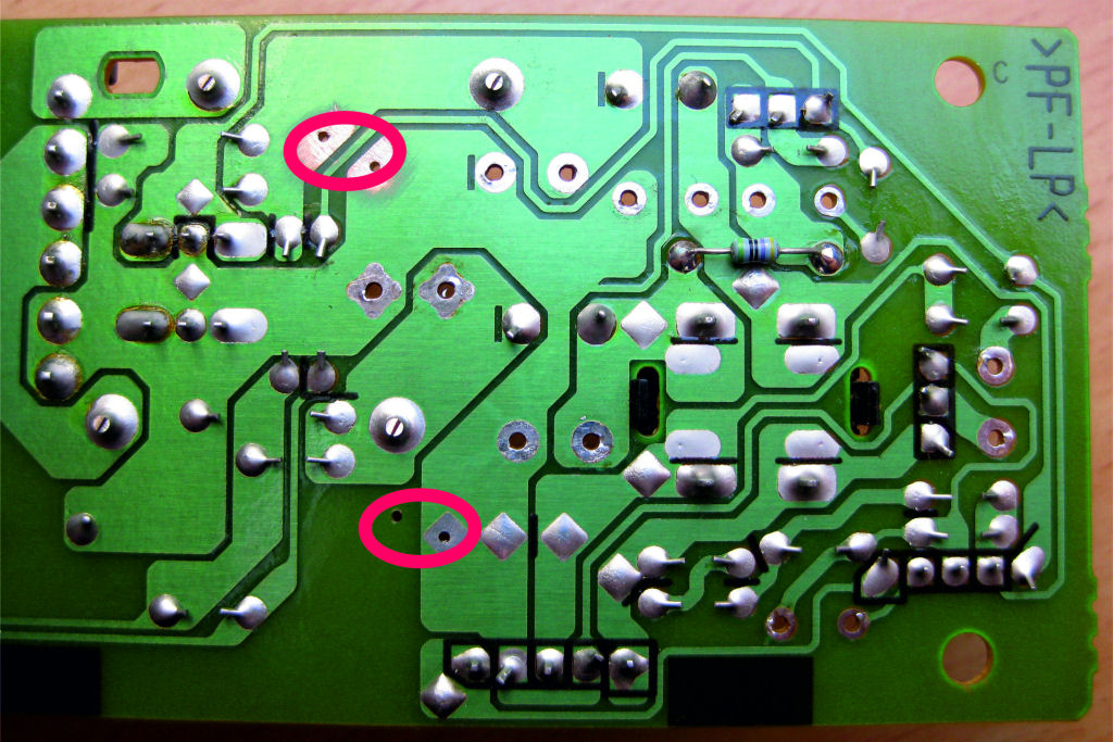
Secondary side everything desoldered cleanly.
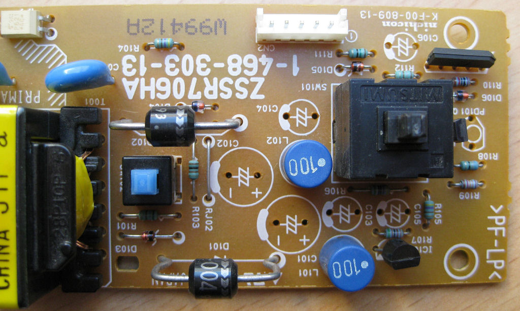
secondary side
Two additional electrolytic capacitors increase the total capacity from 8800µF to a whopping 13200µF.
To do this, simply expand the circuit board by four holes. See markings!
The 2200µF electrolytic capacitors should have a diameter of 10-12mm, otherwise things will get tight.
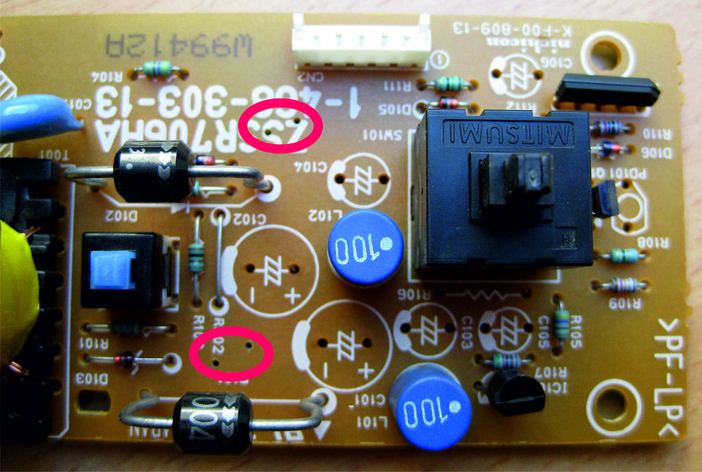
It is best to drill the holes from the conductor track side in order to achieve precise placement.
So now everything can be assembled as shown.
Please pay attention to the polarity of the electrolytic capacitors.
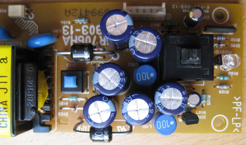
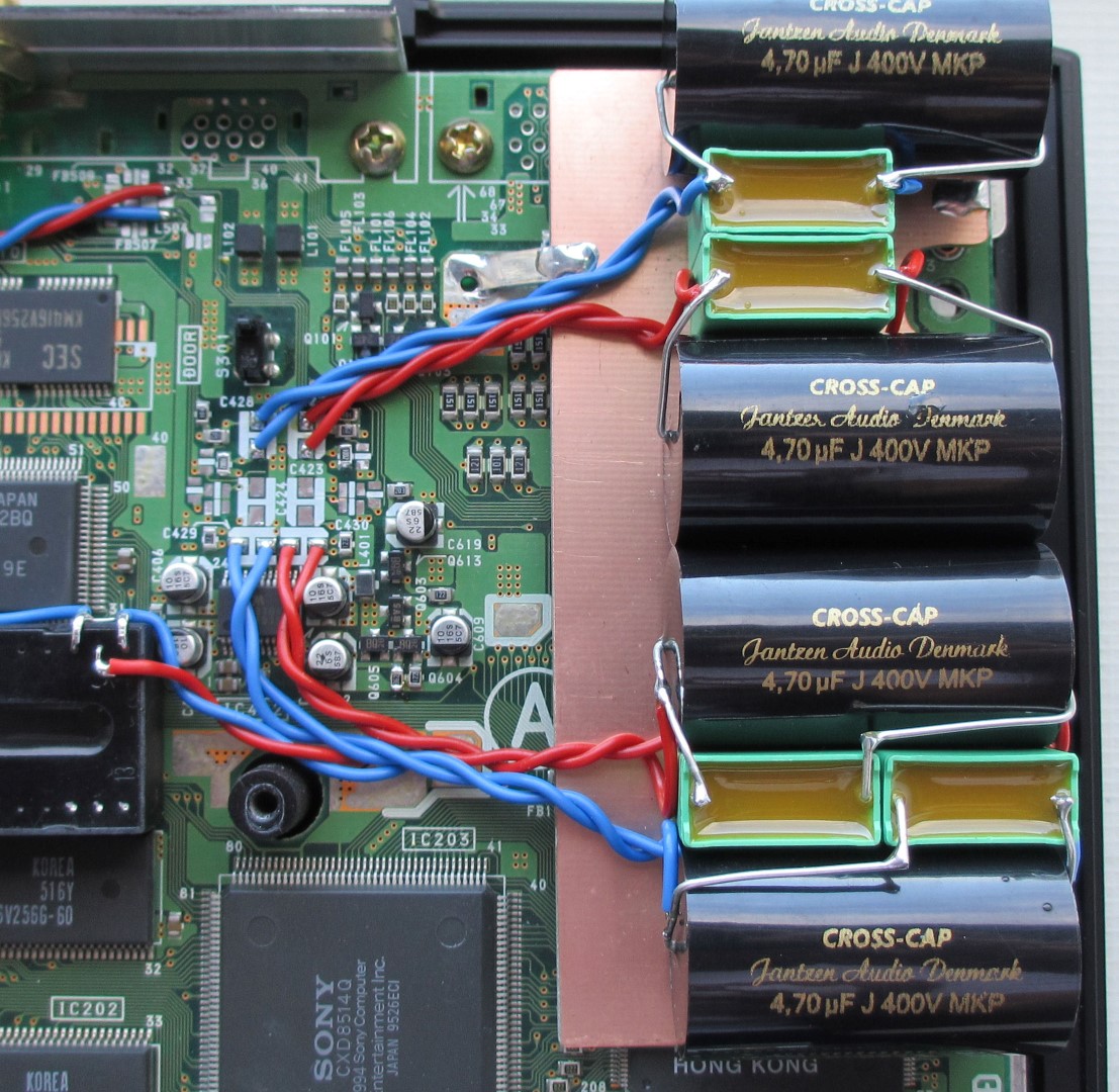
Foil capacitors are connected parallel to the electrolytic capacitors.
To the 2200µF Elko's each 100nF.
To the 1µF and 2.2µF each 22nF. The grid dimension of the foils C's shown is 5mm.
The resistor shown can remain on the component side, but then do not press the electrolytic capacitor completely onto the circuit board (distance 2mm). Half of the resistor is under the elko.
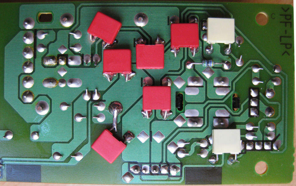
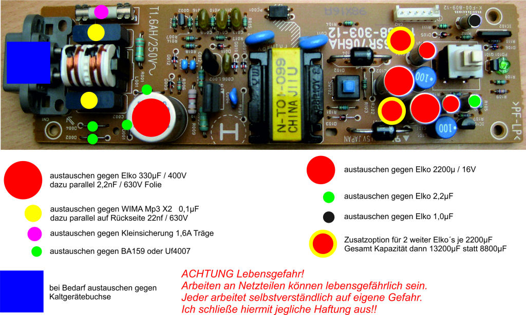
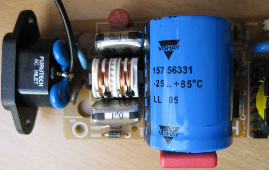
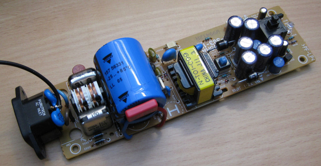
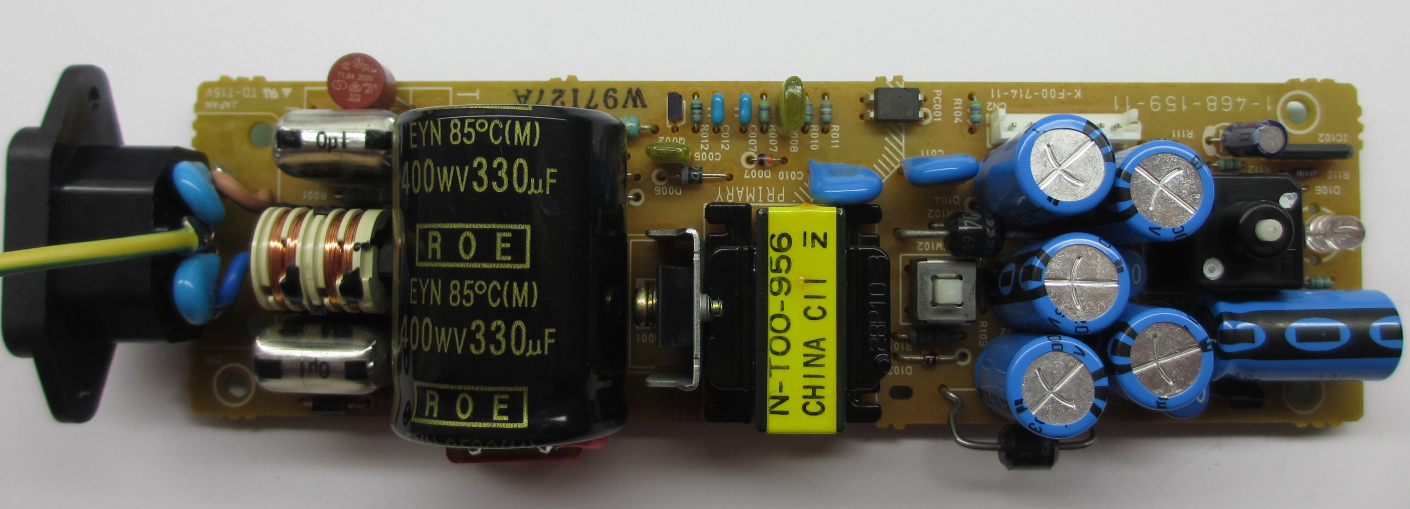
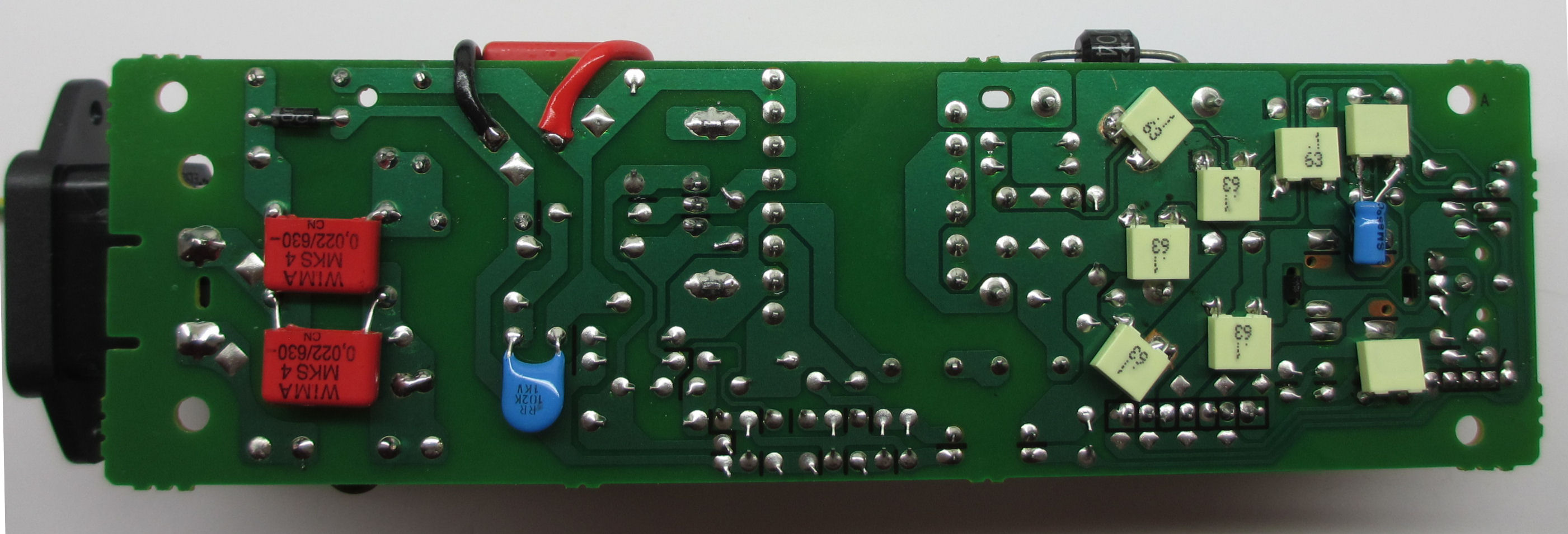
primary side
Everything soldered clean.
As you can see, the components have already been used.
As you can see here, the old capacitors are simply glued onto the circuit board. They serve as spacers for the large charging capacitor, which is placed horizontally. So you don't have to move any components to the back of the board.
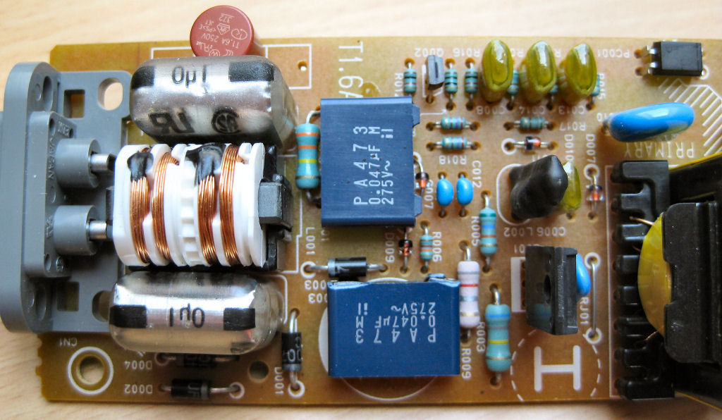
So, just stick Elko on it and you're done. Switch the WIMA 2.2 nF capacitor parallel to the electrolytic capacitor and solder it to the PLUS and MINUS on the circuit board.
The Elko 330µF/400V has a diameter of 30mm and is 40mm long. In the case of larger dimensions, components must be relocated and moved to the rear. It is also possible to use a 1000µF electrolytic capacitor. In my opinion, 1000µF is far oversized.
A 22nF / 630V is connected in parallel to the MP3 X2.
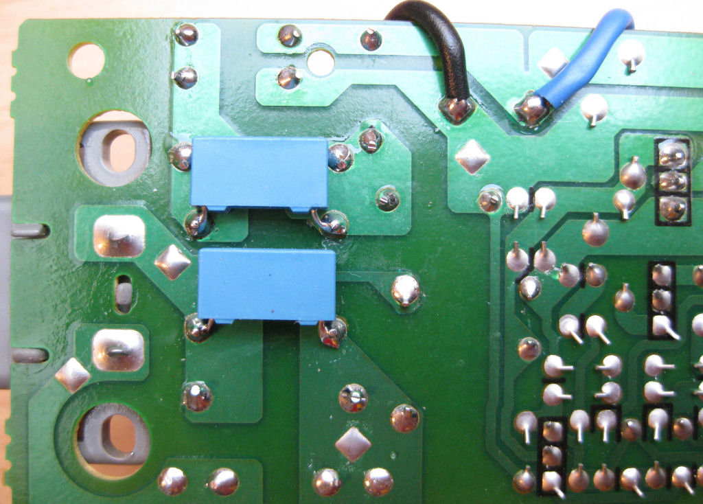
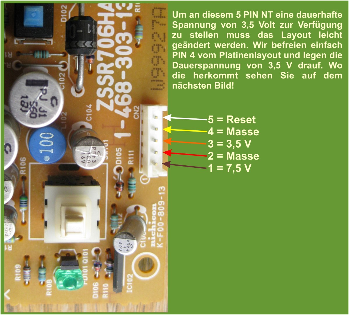
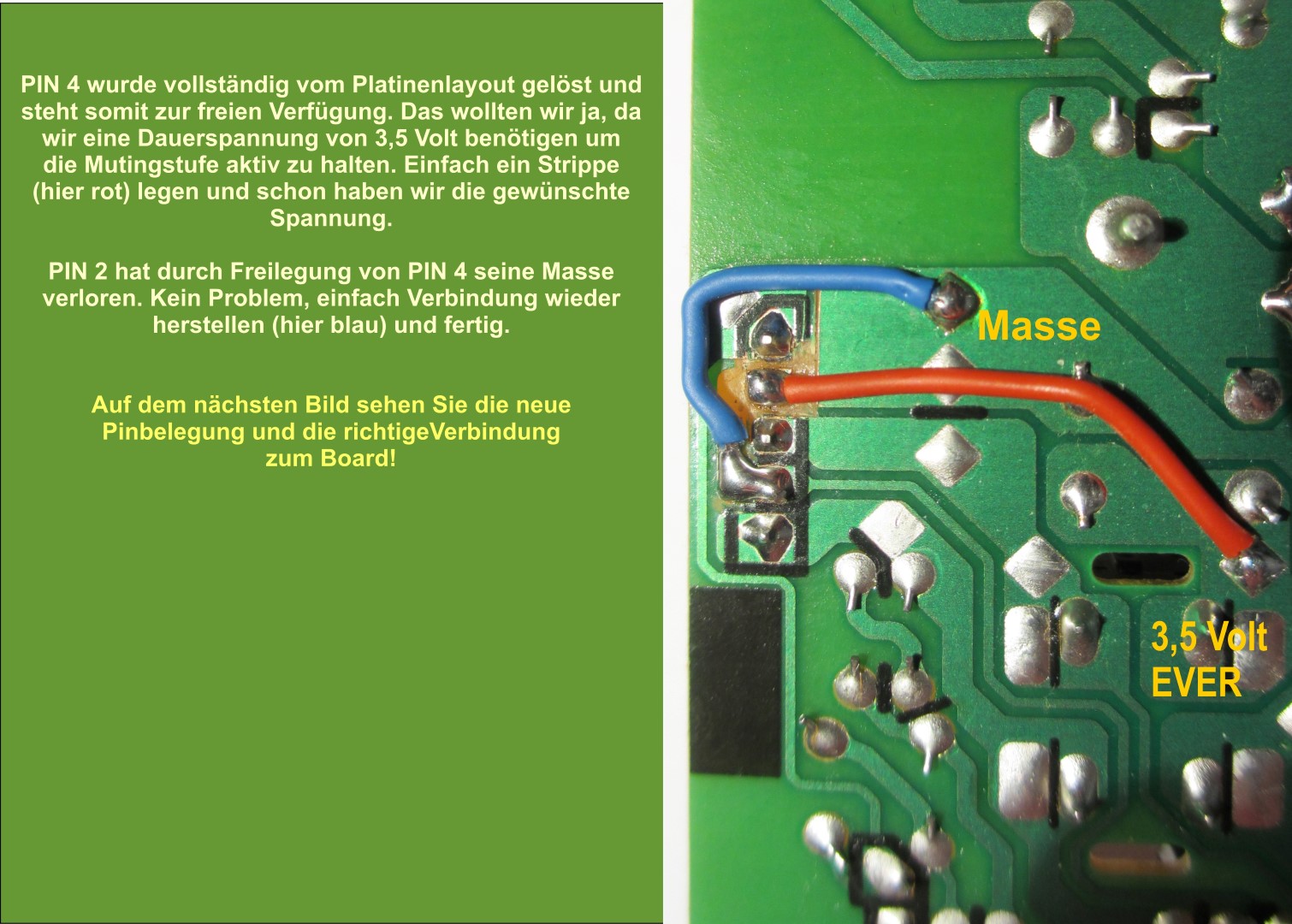
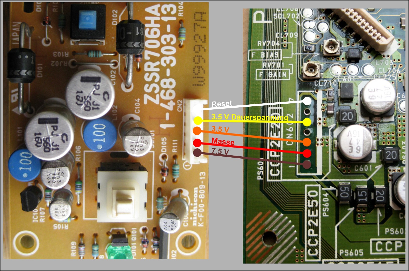
Here is the correct connection from the 5PIN power supply to the mainboard.
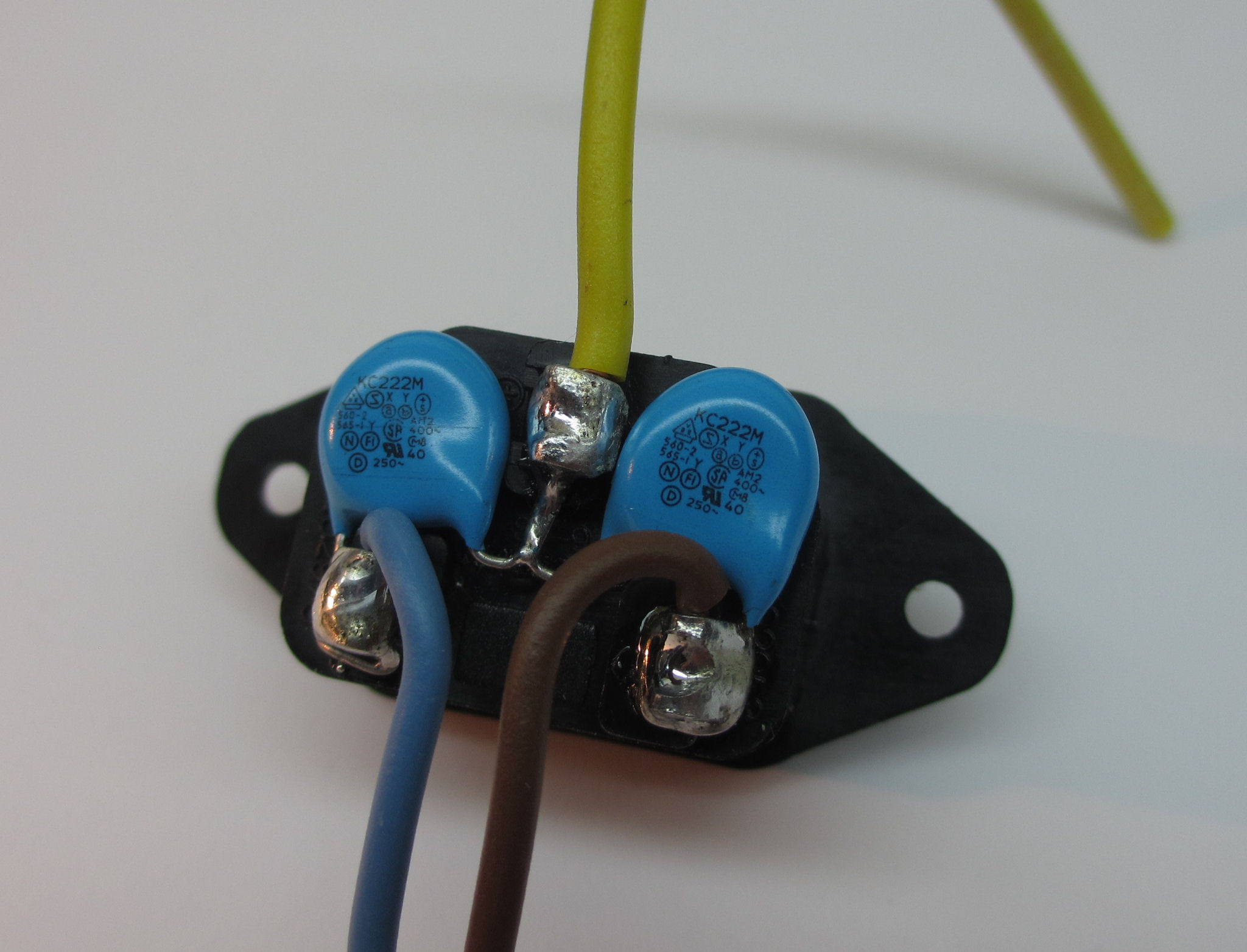
If you want, you can replace the old mains connection with a fully grounded IEC socket. The two Y-KERKO 2.2nF are clearly visible
Made! Yay... and all without magic...
A self-modified 5-pin power supply for your Playstation, and all that for very few euros .
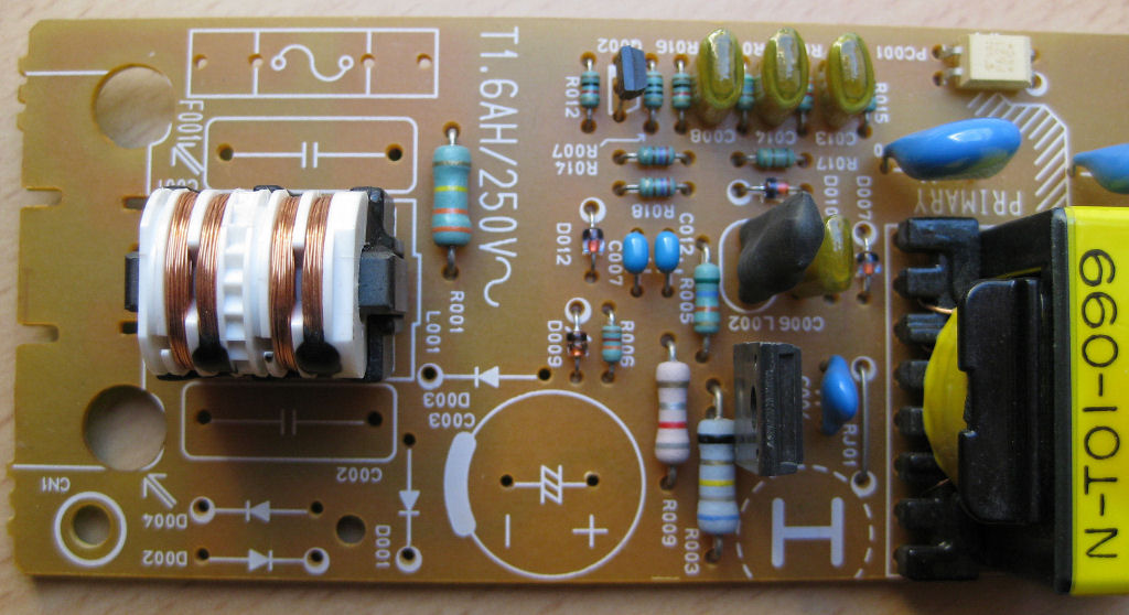
Here is a power supply with a 7-pin connector
Mainboard
According to the method shown here, only what I consider to be the most sensible changes are made.
Attention, the conductor tracks are very sensitive and tend to detach from the circuit board if soldered for too long. Therefore, solder as short as possible, preferably with a good desoldering pump and desoldering braid.
Good luck with the modification of the 21, 22 and 23 boards. 11 board slightly different!
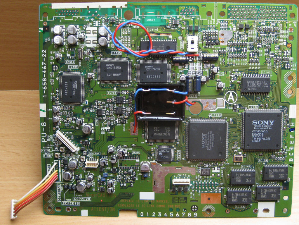
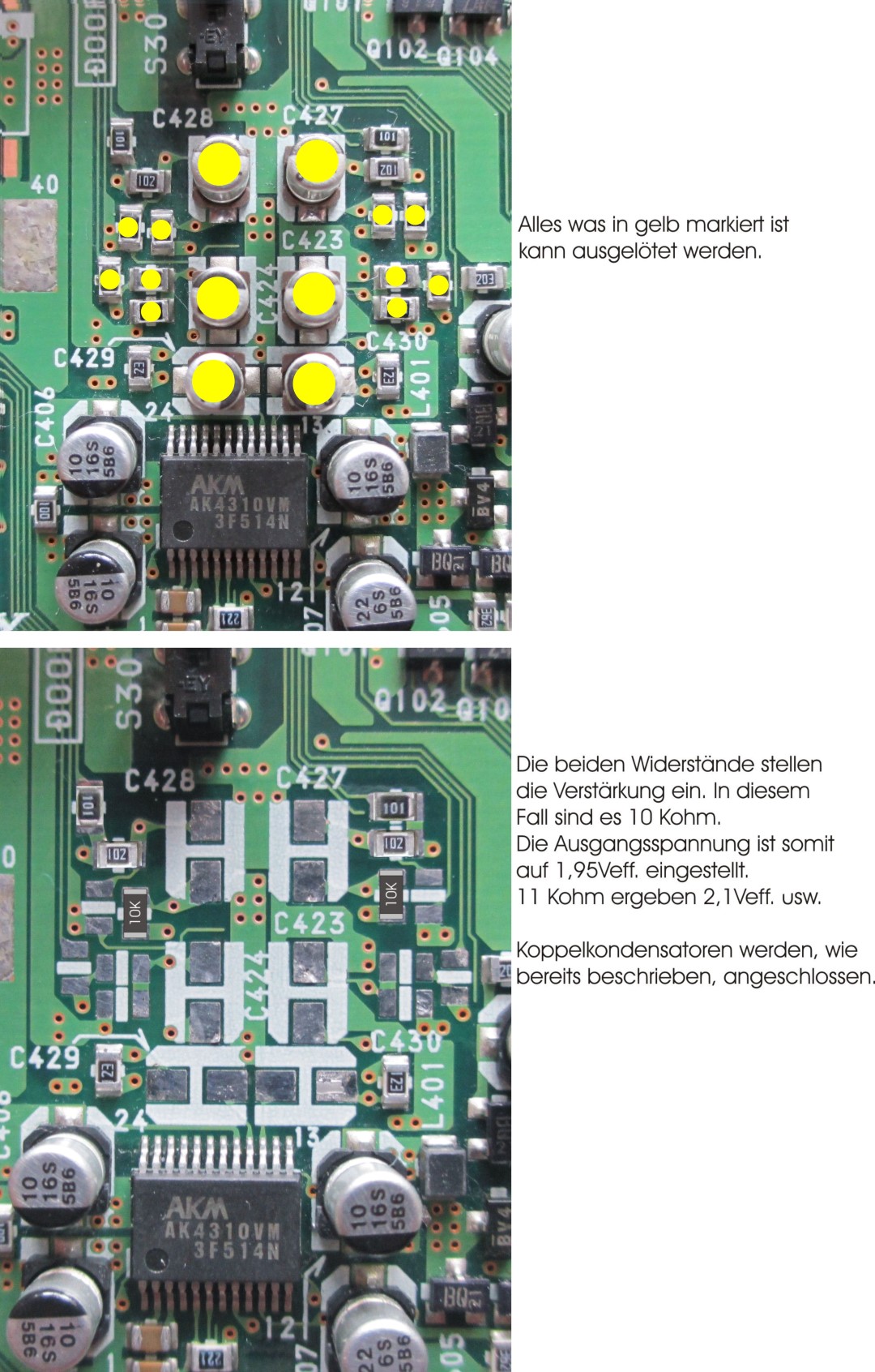
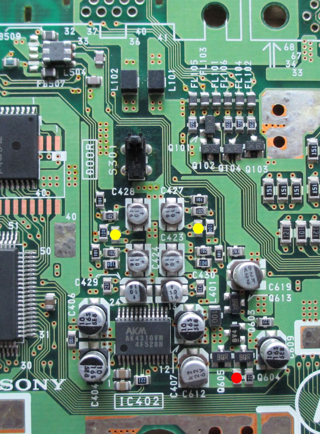
As you can see here, some areas are marked on the top of the board. It is precisely in these areas that soldering work is required.
Interfaces are no longer required and can be unsoldered.
Furthermore, several resistors, capacitors, the RGB encoder, video DAC and the associated RAM components are removed. Thus, the video stage is completely disabled, the so-called channel separation is completed and the output voltage, depending on the option, is increased. Finally, unsolder the connection for the power supply if you want to solder in the connecting strips directly. Otherwise, just ignore it and leave it in. So, all components marked in red can be easily removed!
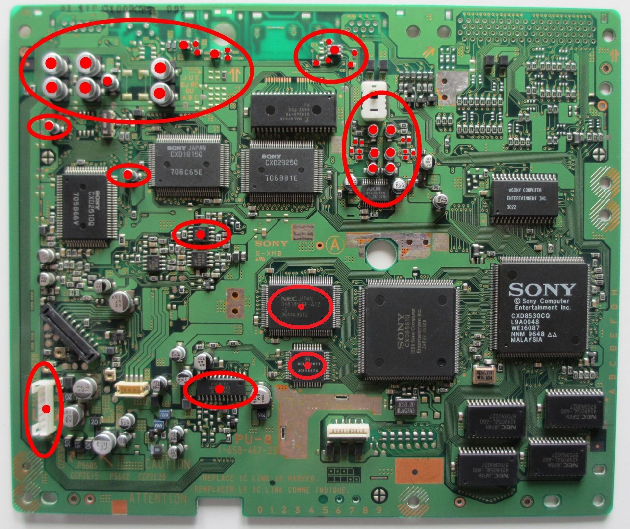
This is what it looks like when everything is prepared! This scheme basically applies to all boards! Only the amplifying resistors, marked yellow, are to be selected as follows: 21, 22 and 23 board = 33KOhm ---- please use 10KOhm for the 11 board! The output voltage is then approx. 2Veff. So, CD player usual. Placement of the coupling capacitors, see example at the bottom!
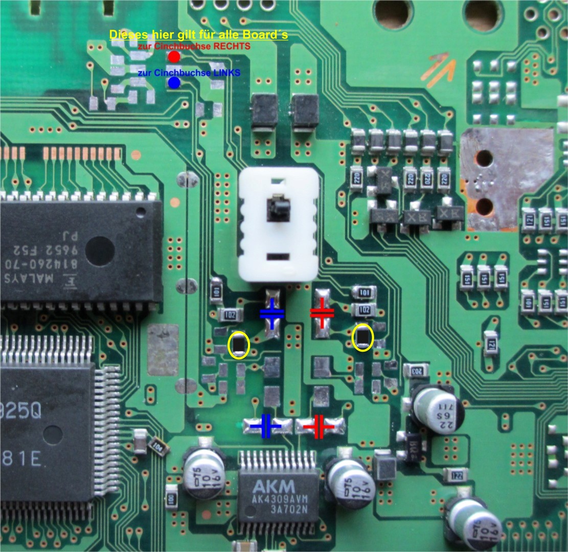
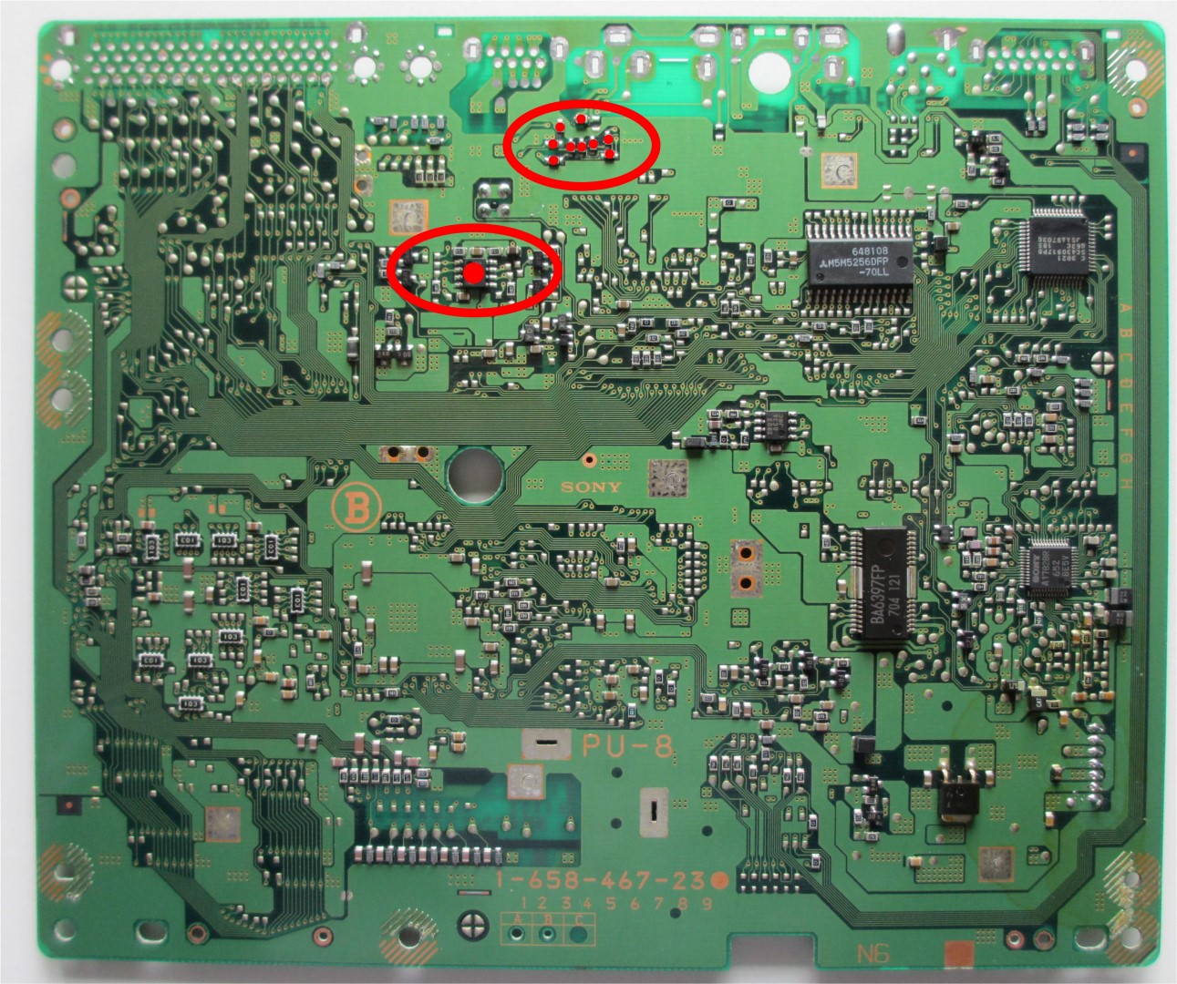
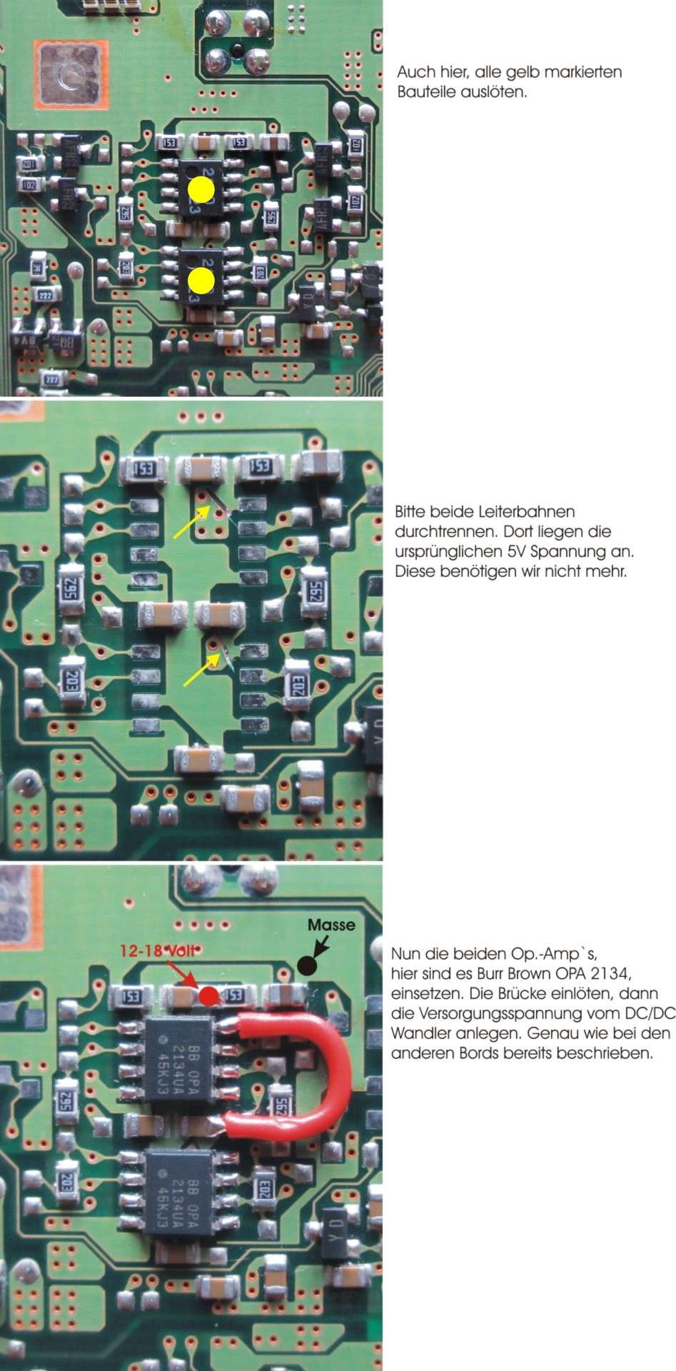
Op. Amp. is desoldered and the conductor is severed! Thus, PIN 8 of the op. amp. without power supply and is available for the new supply by means of a DC/DC converter, 12 volts.
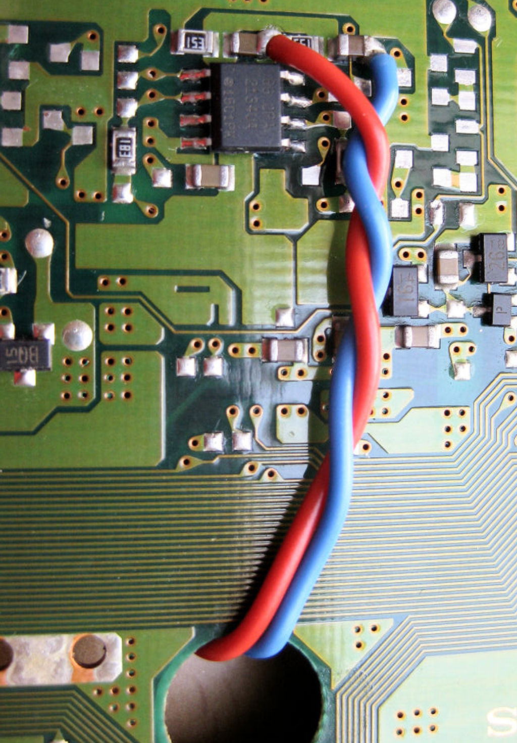
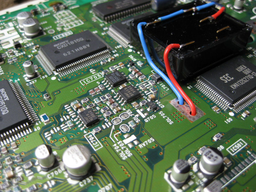
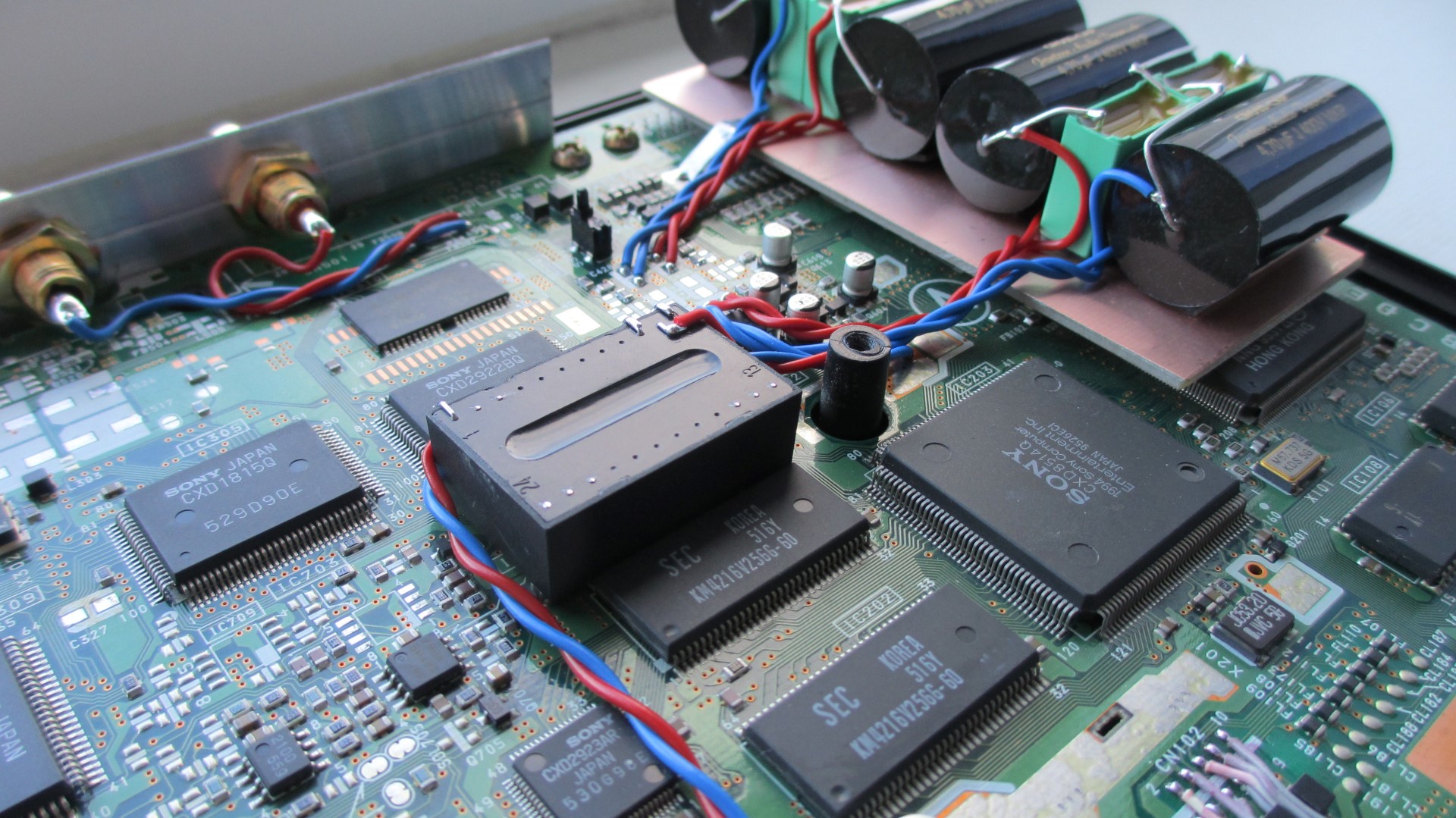
Clearly recognizable here, the high-end Burr Brown OPA2134 op. amp. is soldered in and the wires are already attached..
The two strands are approx. 15 cm long and are inserted through the round opening on the top of the board. They will later be connected to the DC/DC converter placed on top.
Whether you use the Burr Brown OPA2134 or prefer another is up to you. Caution, not all are compatible with each other. Please check beforehand.
The op. amp. is supplied with a DC voltage of 12 volts. For this I use the pictured DC/DC converter. It supplies a maximum current of 100 mA. Enough about several op. amps. to operate simultaneously. It is also small enough and finds enough space on the board. However, other types can also be used.
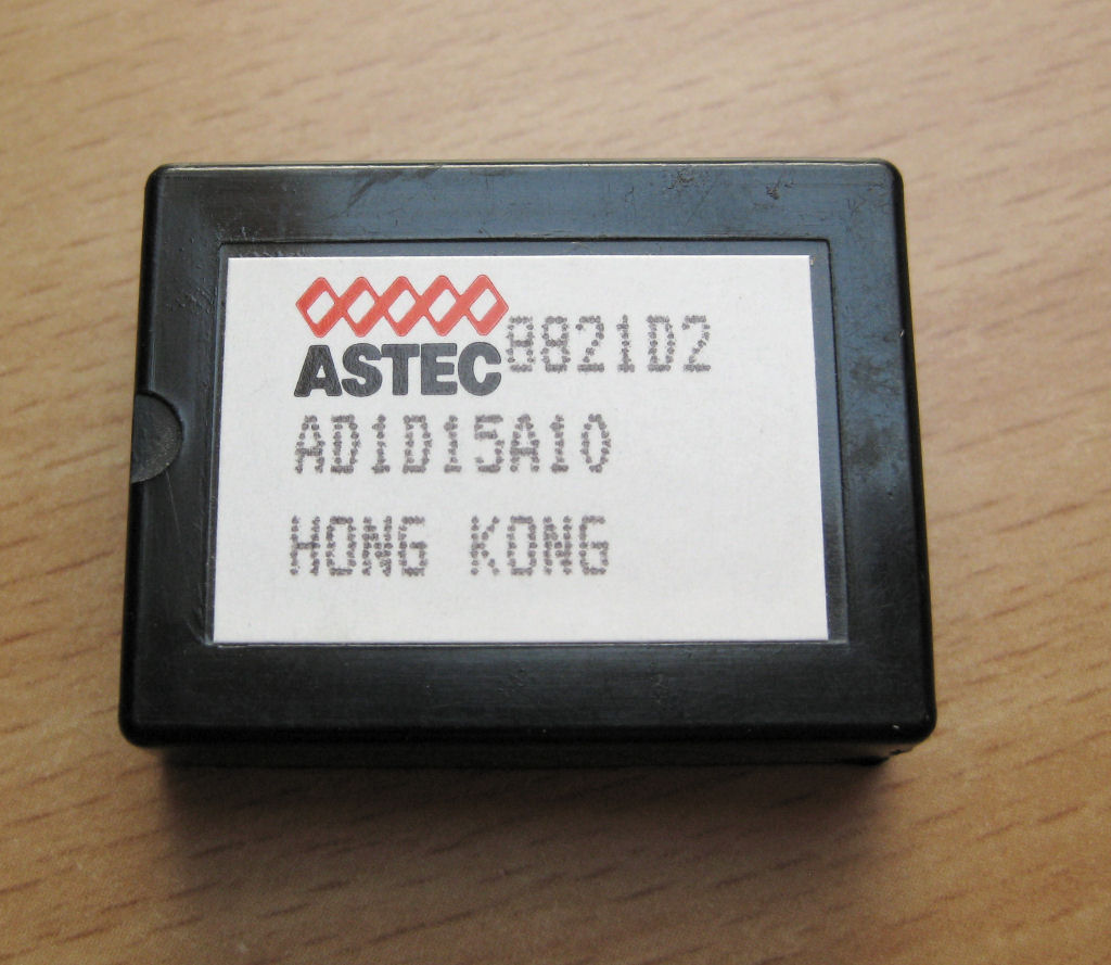
And a place has already been found where the DC/DC converter can live. Simply attach with double-sided tape and you're done.
The two strands on the right lead directly to the Burr Brown op. amp. and in the shortest way.
The voltage of 5 volts for the operation of the DC/DC converter is connected on the left.
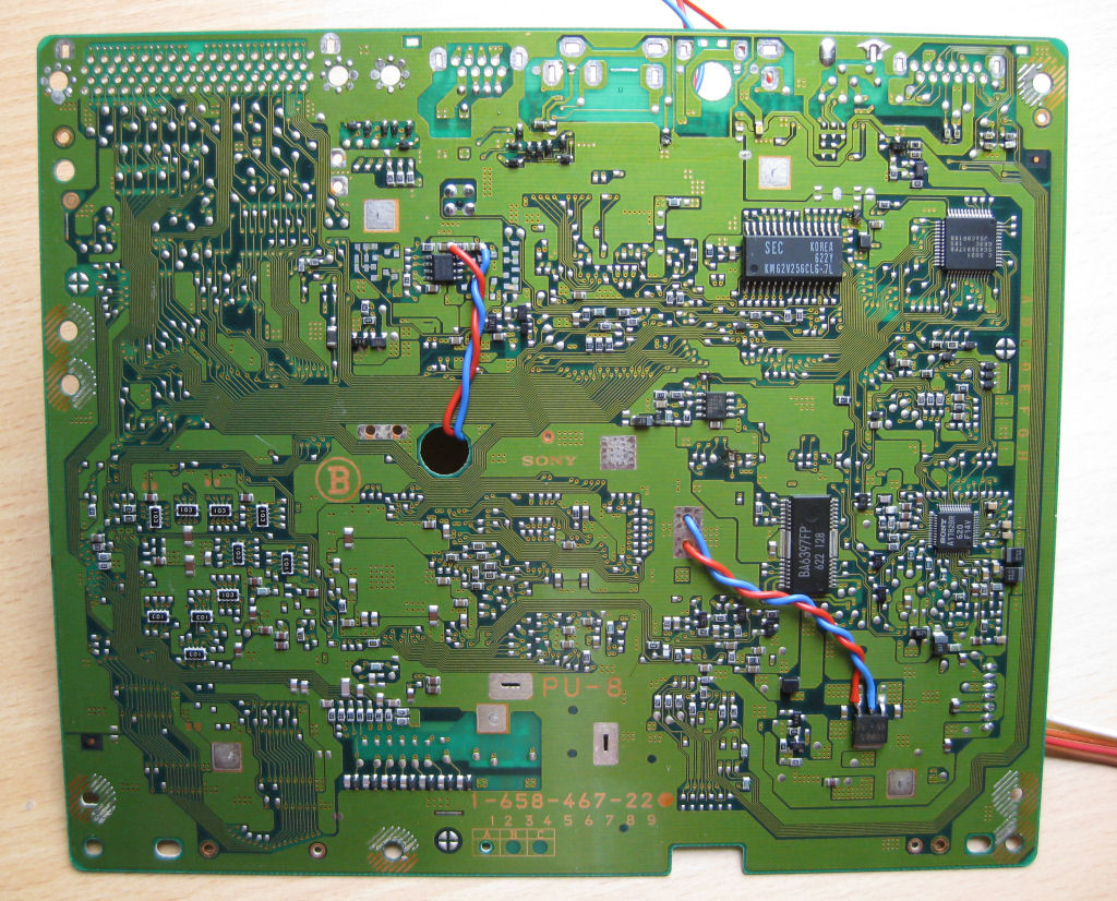
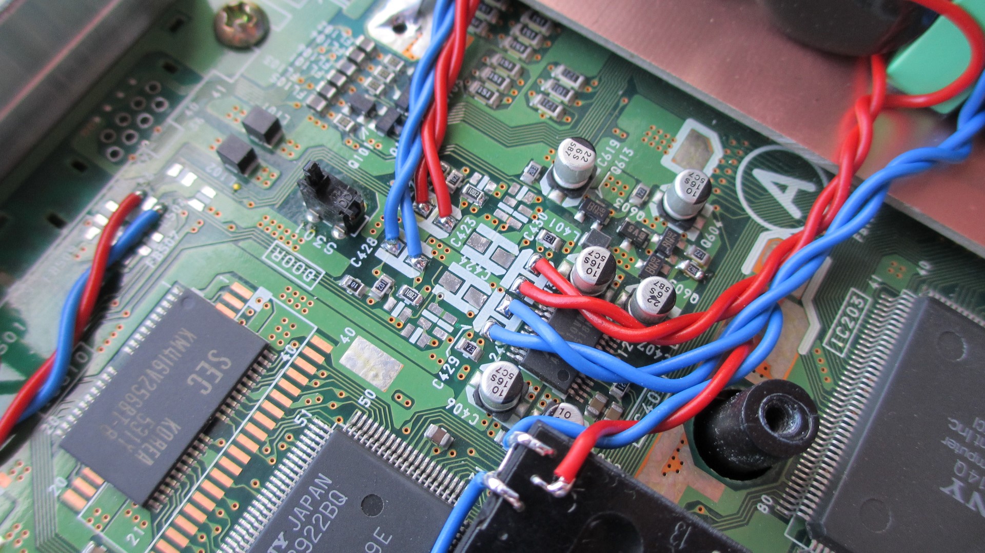
The next illustrations show exactly where the strands run and where they are connected.
Pass the two strands through the holes and connect to the voltage regulator on the other side. Please leave strands long enough!
At the bottom right of the picture is the voltage regulator that provides the board with the 5 volt operating voltage.
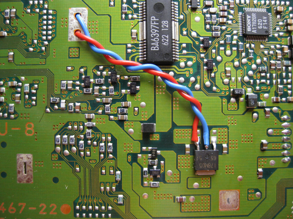
Here in an enlarged view.
The 5 volt supply voltage for the DC/DC converter is taken directly from the voltage regulator.
red = positive
blue = minus
Example placement of the coupling capacitors! Jantzen CROSS-CAP 4.7µF MKP // Vishay MKT 10µF.

Circuit diagram of the output stage of the PU-8 21er, 22er and 23er board!
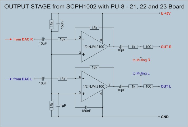
SCPH-1002 11er board with Burr Brown OPA2134 approx. 2Veff. output voltage
Is the op. amp exchange possible with the 11er board, which has two of them?
That's fine. Just do it exactly as you see on the instructions here.
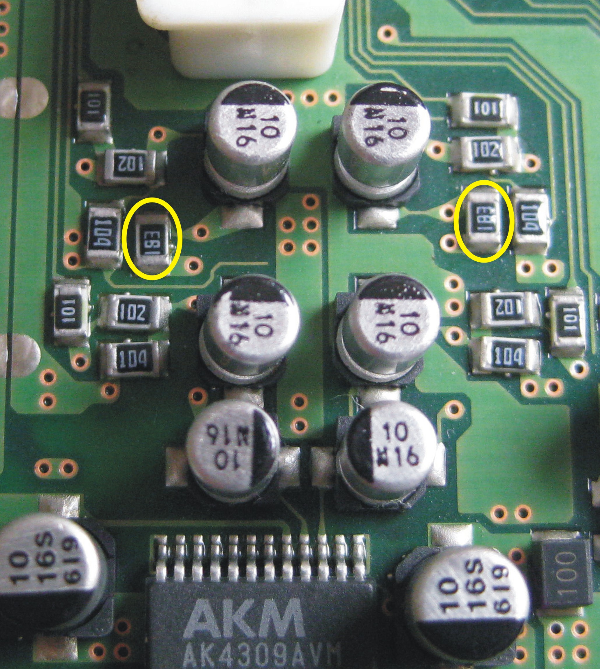
21er - 22er - 23er Board 1.7Vrms. output
The simplest way to increase the output voltage on a series device with a 21, 22 or 23 board, with or without replacing the coupling capacitors, is to replace only two resistors. This gives you an output voltage of 1.7 Vrms without distortion! Due to the low supply voltage of the op. amp. from only 5 volts, a further increase is not possible. Unless you work with DC/DC Converter and replace the Op.Amp. as already described in detail on the previous page. However, it doesn't make sense to set the output voltage to over 2.00Vrms. unless you want to severely limit the range of your volume control, scrap your amp, or win the world championship in boosting output voltage!
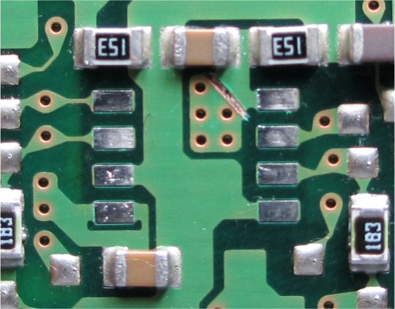
Here you only have to replace the two resistors marked in yellow with 27KOhm type 805, and you're done! Of course, this does not have the slightest influence on the sound.
With the 11 board there are two ways to increase the output voltage.
- Either only remove the resistor, marked in red. Output voltage = approx. 1.5Vrms.
or...
- Only replace the resistors marked in yellow with 7.5Kohms = approx. 1.7Veff.
Laser Unit
With immediate effect! Simply bid for a PSone SCPH-102 for little money, remove the KSM-440-BAM laser unit, replace the gray cover of the laser unit with the old one from the SCPH-1002 and install it in the PS1. So far I hadn't caught a single one that wasn't working properly. Why? Because the PSone is a few years younger and the laser unit has never been exposed to the power supply heat. As is well known, the PSone (so-called lunch box) was operated with a plug-in power supply unit. If necessary, simply clean, lightly grease the running surface, and you're done! And, you have an original SONY drive and not cheap Chinese junk. But if you don't want to miss out on the fun of handicrafts, simply read the following chapter and then decide which option to choose.
When we replace a worn-out KSM440ACM laser unit with a new one, it often becomes problematic.
Original Sony laser units are no longer available. So what to do? Oh yes, there is something from the Chinese. They build everything...
However, it is safe to mention that these replicas are inferior goods. You have to ask yourself why you don't get flawless goods for flawless euros.
My experiences with these China replicas:
At least 50% not executable, although the providers write "tested before shipping"
The most common series errors: Motor does not run, gears do not mesh and do not transport the carriage, the support plate is crooked on the spindle and gives the CD a huge radial run-out, CD only runs halfway and breaks off, loud running noises, etc. etc. etc.
But we're not stupid!!!!
Then we simply build an original Sony REMAKE. As? Very easily!
If you have enough soldering experience and good eyesight, you shouldn't have any problems here.
Of course you buy a China clone first. These have a brand new laser chip with the associated flex circuit board. This unit is removed from the drive and set aside. You can safely dispose of the rest, as they are completely worthless.
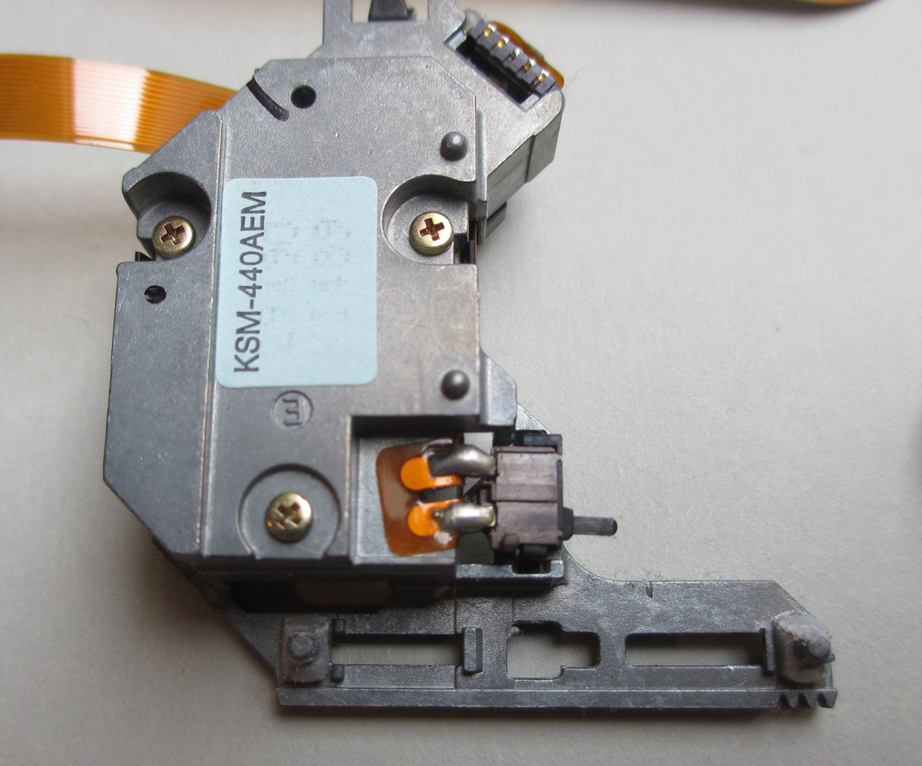
Anyone who deals with the PS1 has certainly collected some non-functioning drives. Thank goodness too! Anything except the KSM440AAM can be used as a basis. All have an aluminum slide.
==The KSM-440-AAM is the first and only laser unit whose housing is not made of die-cast aluminum. All other models come with aluminum slides.==
You disassemble it by first removing the cover. Then remove the toothed gear and take out the laser carriage. The frame is thoroughly cleaned and carefully checked for signs of wear. If no abrasions are visible on the treads, it can be used as a basis for a REMAKE.
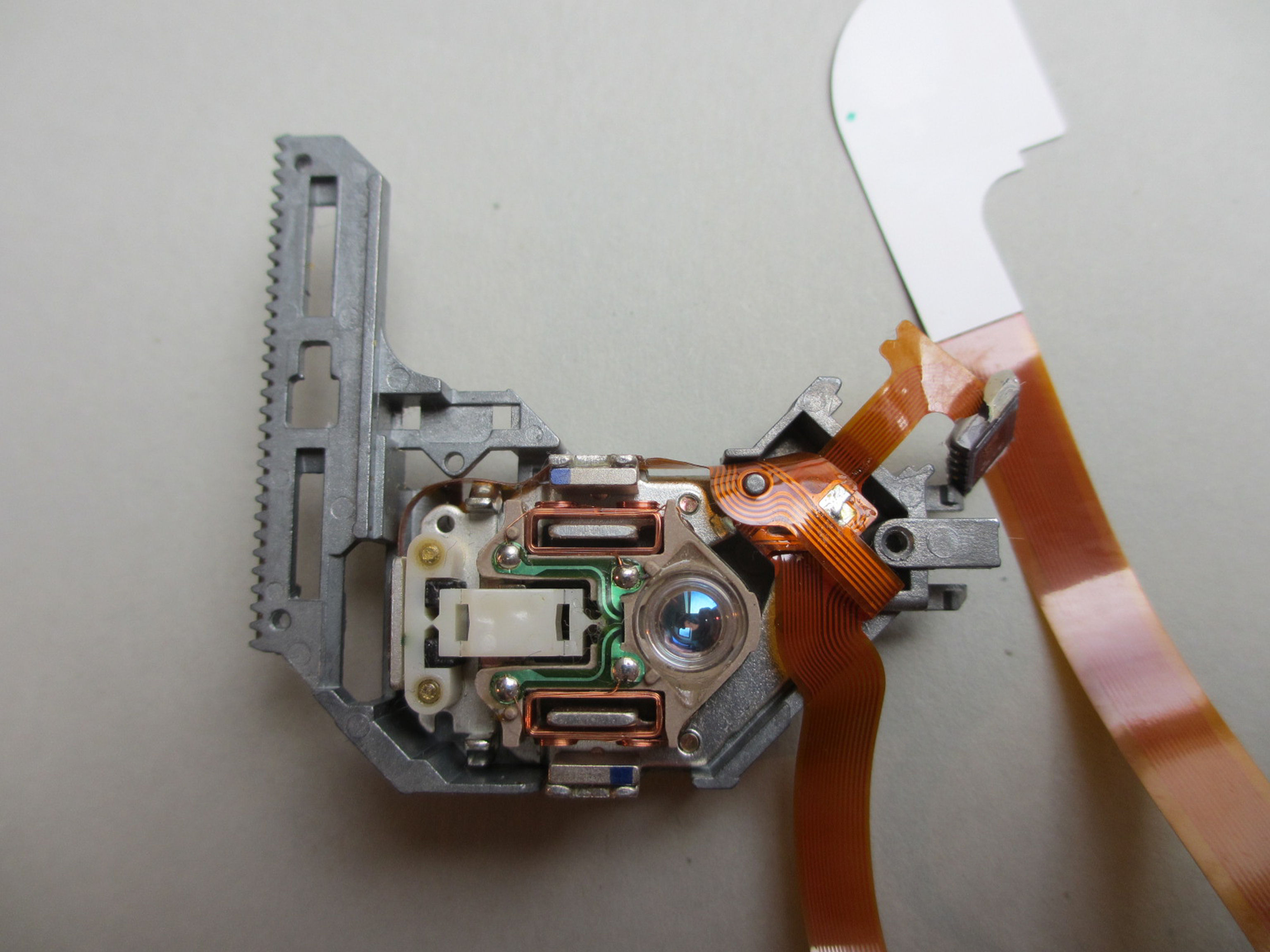
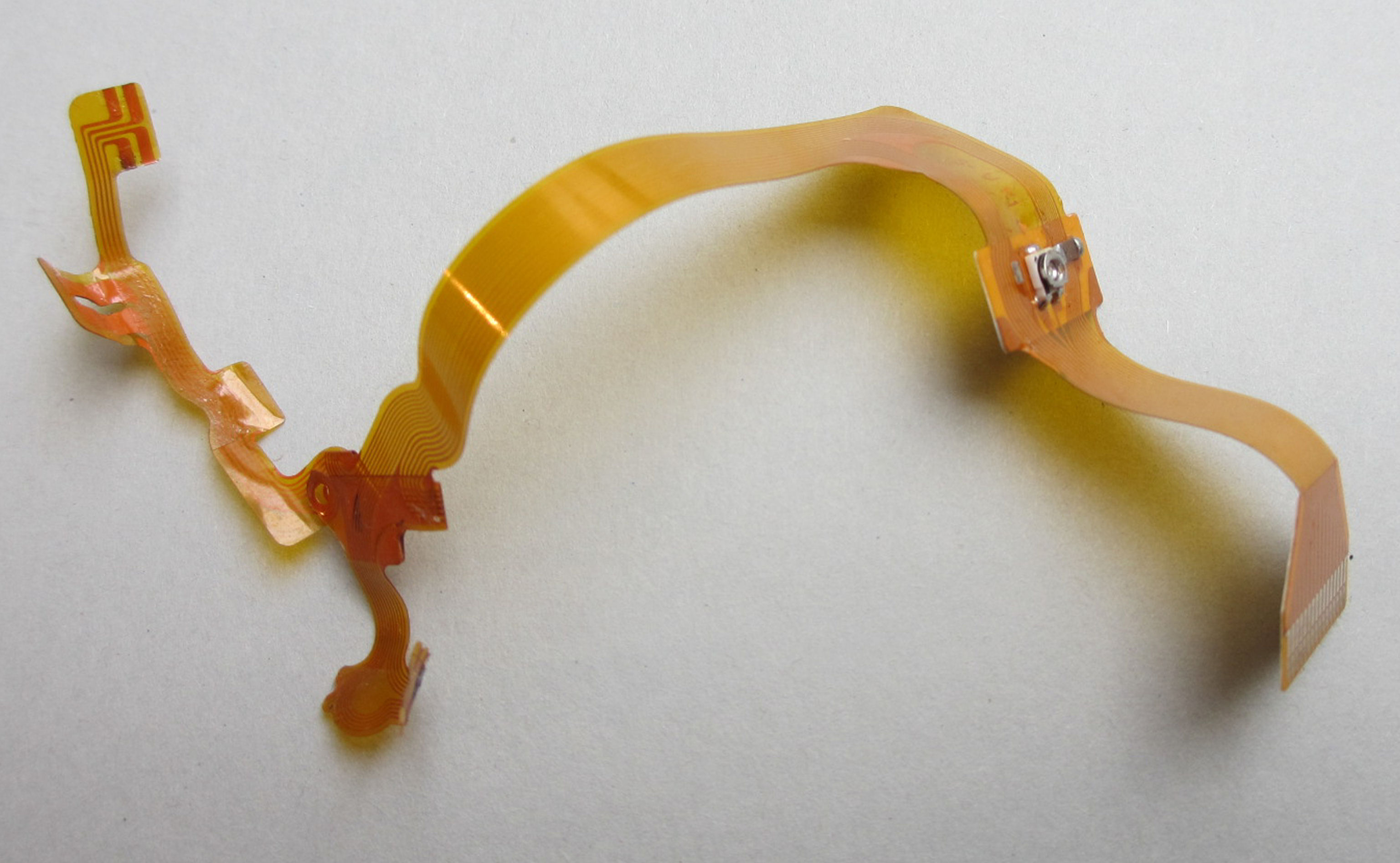
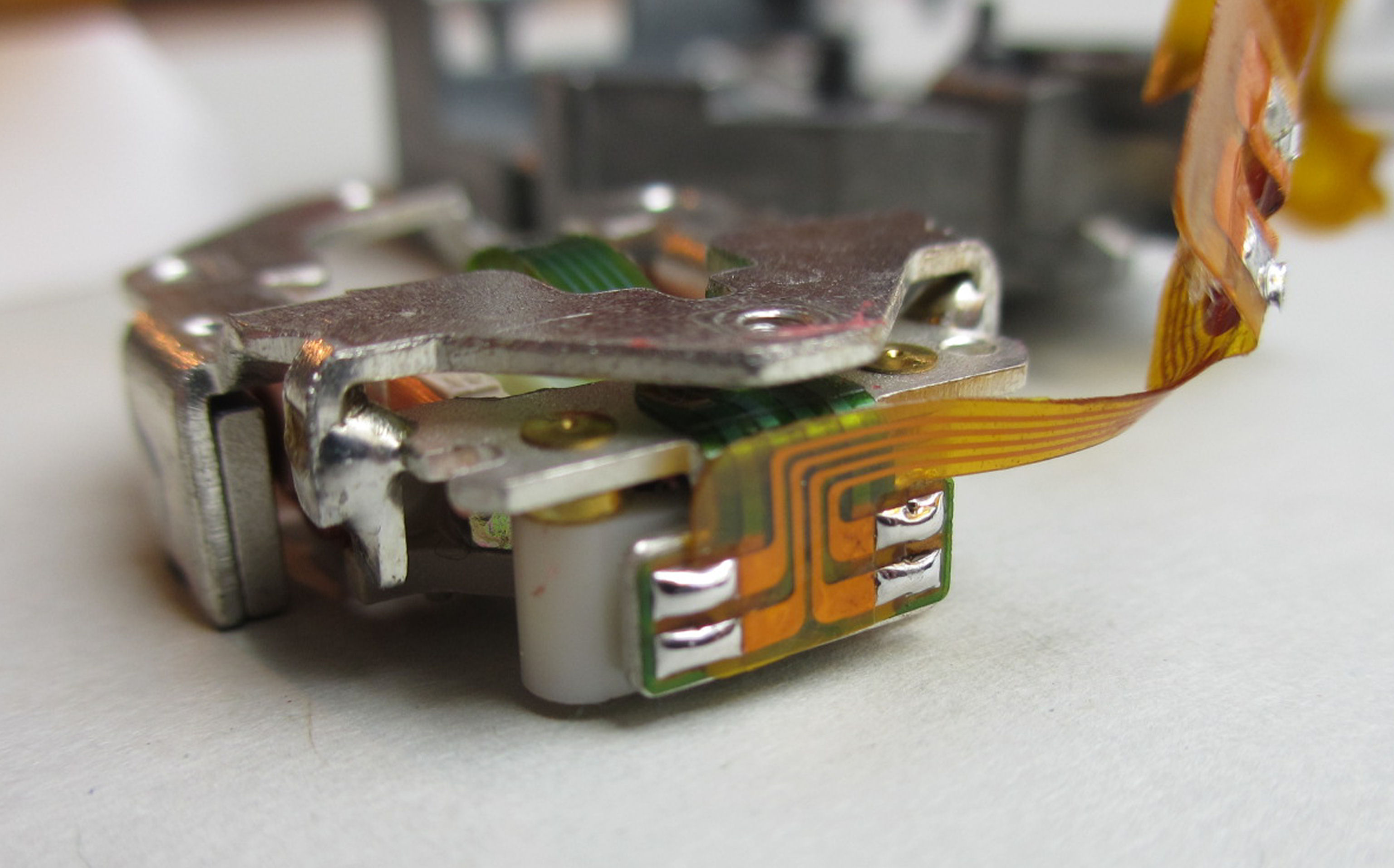
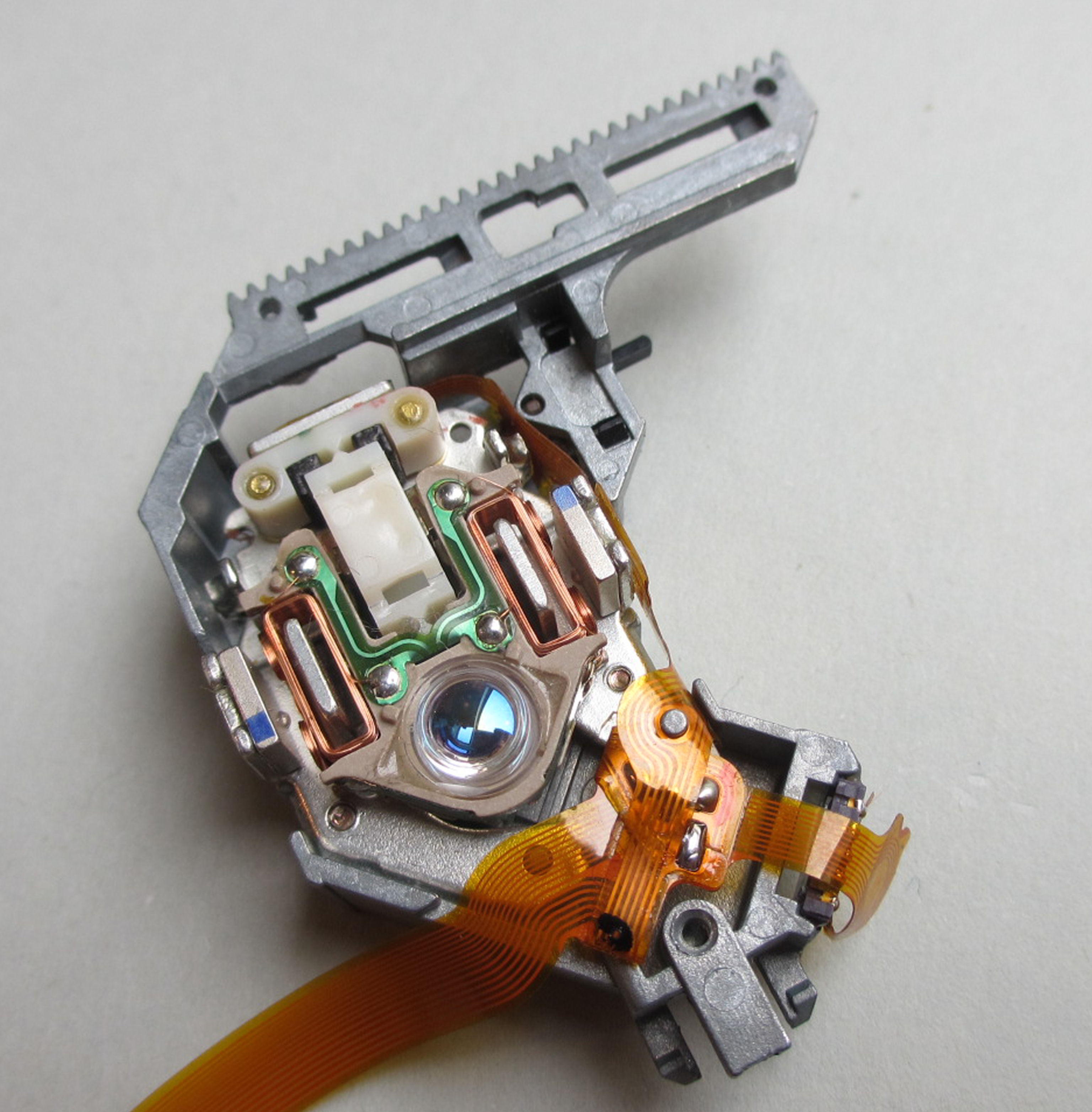
The flexible foil circuit board including the laser chip is now being replaced by the new drive from China. But before that please clean the deflection mirror and the lens from the bottom. It is essential to ensure that the laser chip is placed in exactly the same place. If everything was done correctly, the drive runs right away, and you have a new "Made from NRW handicraft table" original Sony KSM440 laser drive.
Needless to say, every part needs to be thoroughly cleaned and re-greased before it is put back together. I always use white petroleum jelly.
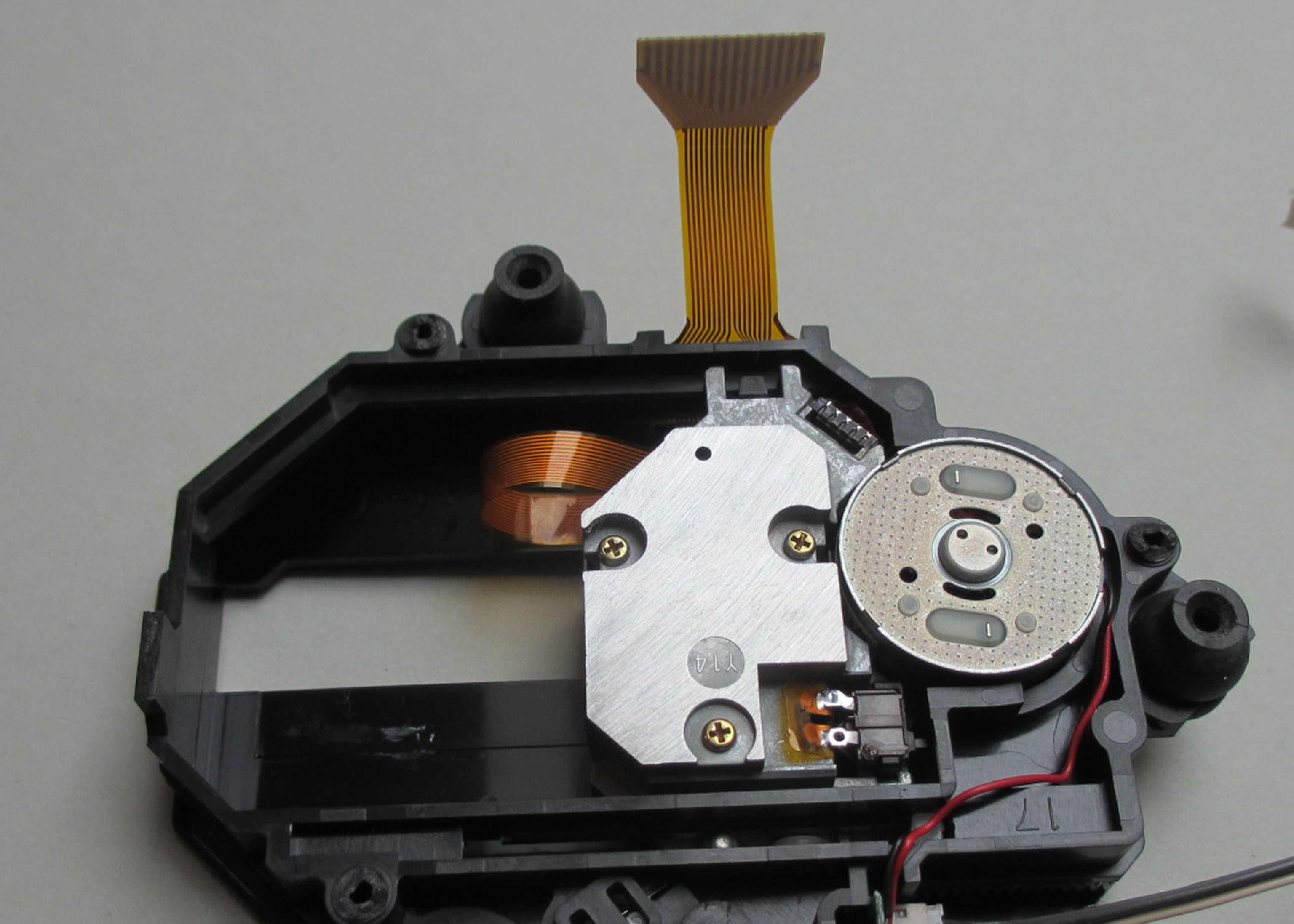
The following images document the process of replacing a new laser cell and flex circuit board.
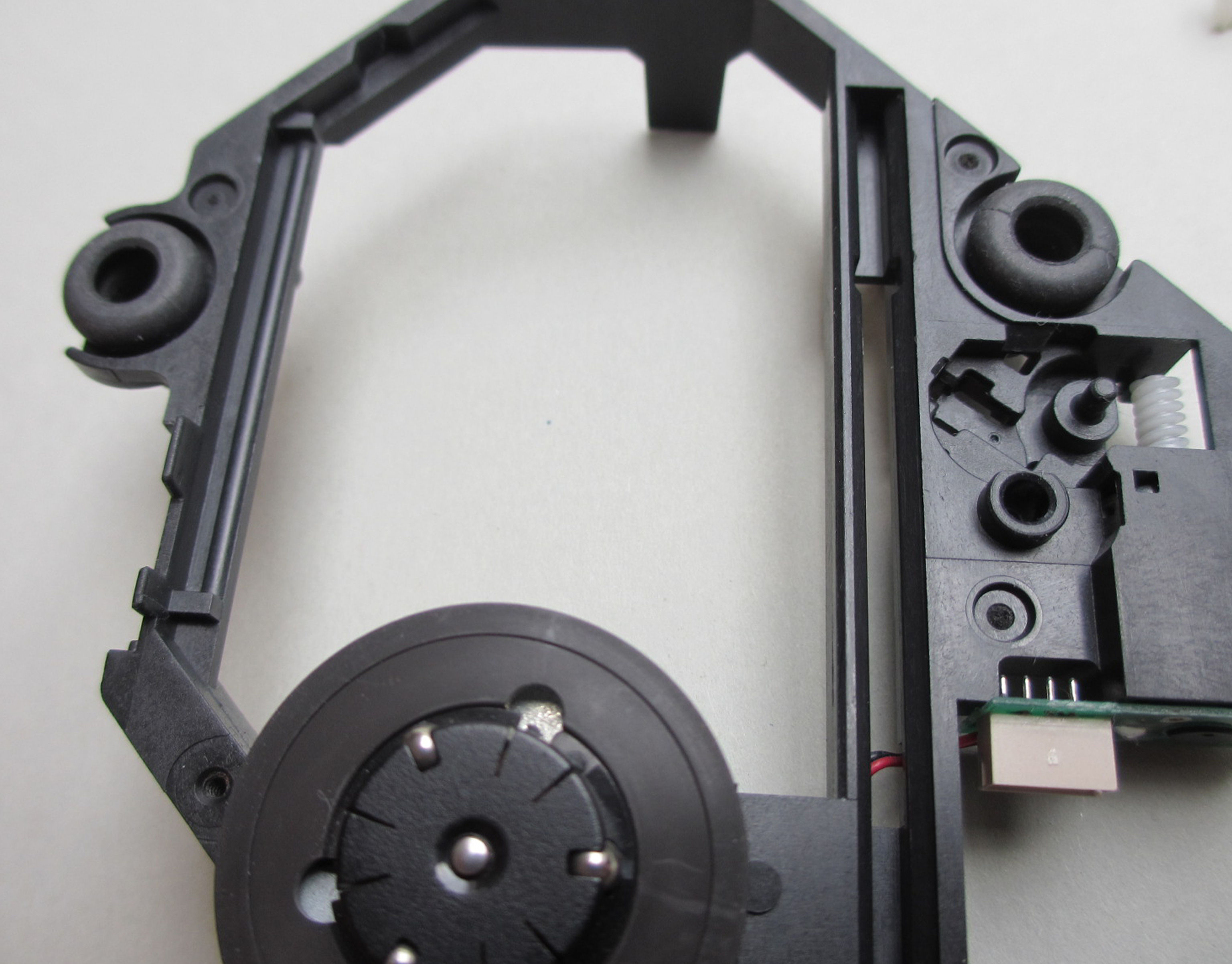
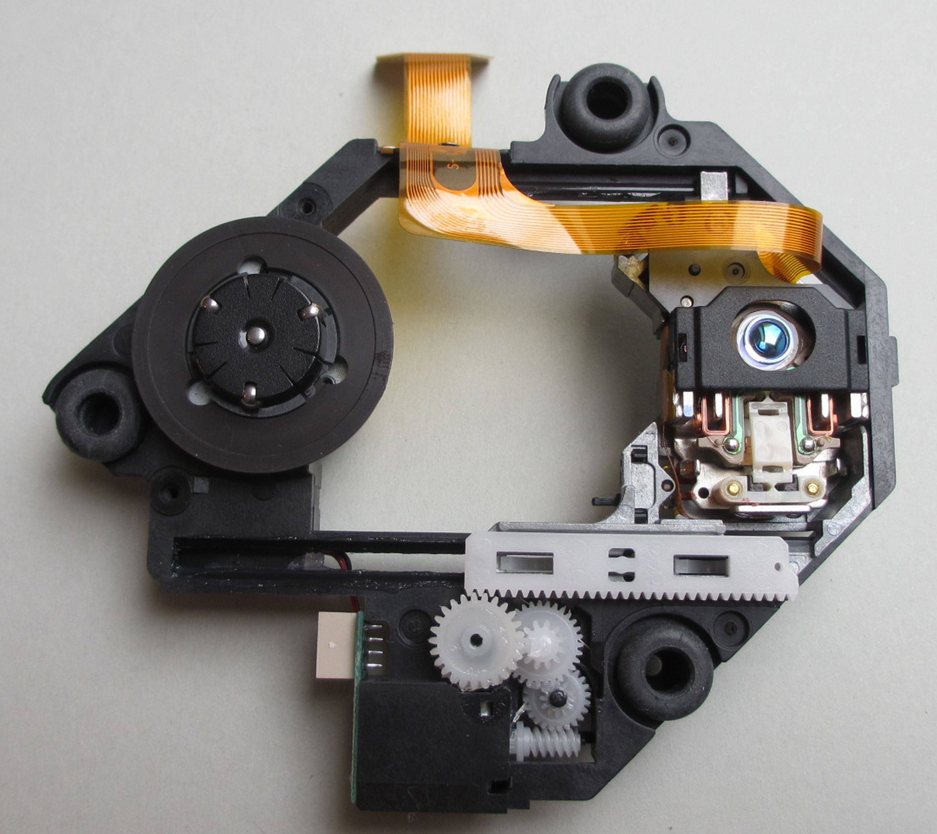
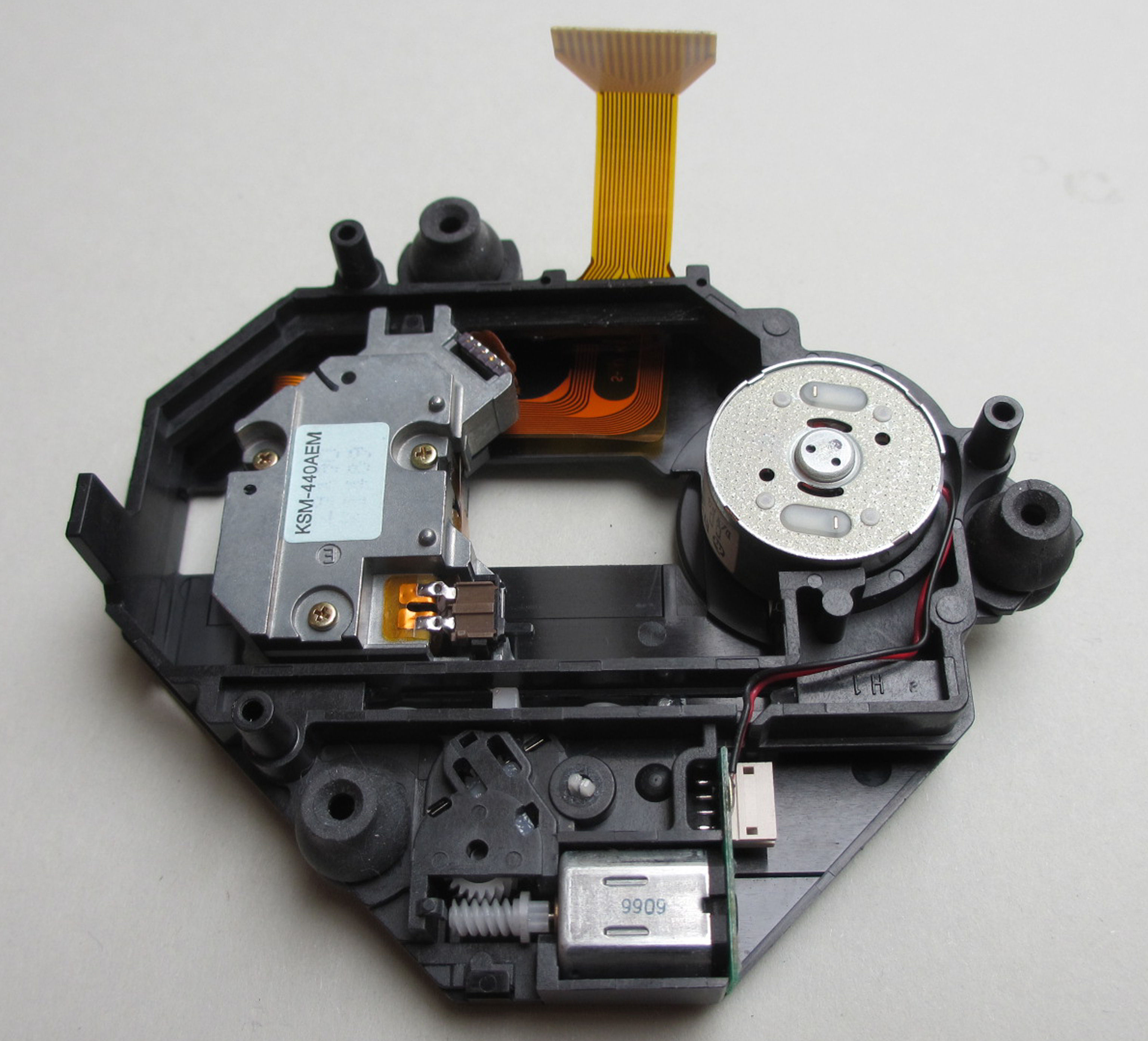
In this example I use a KSM-440AEM drive as a basis. These drives were used in the successor models of the SCPH-1002, were placed far from the power supply, and thus never overheated.
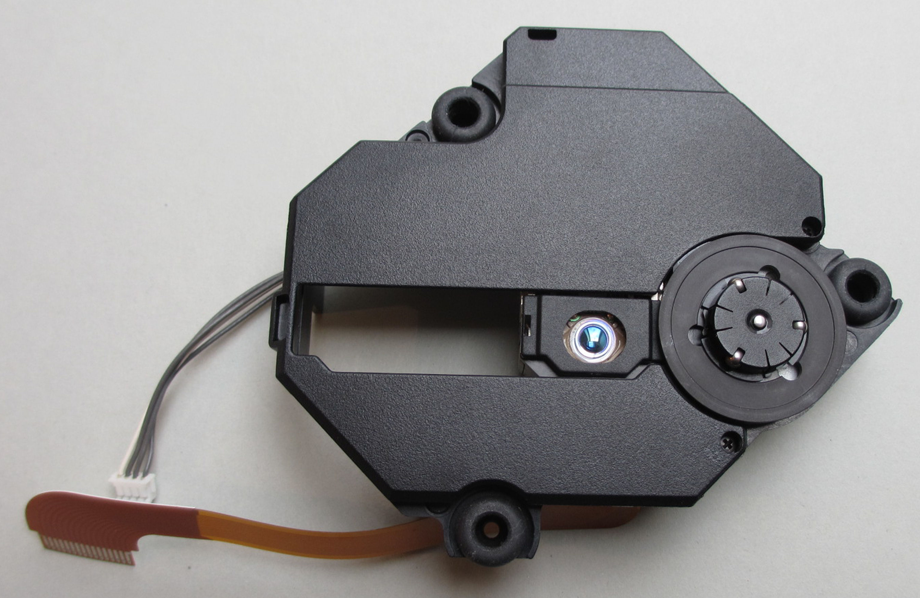
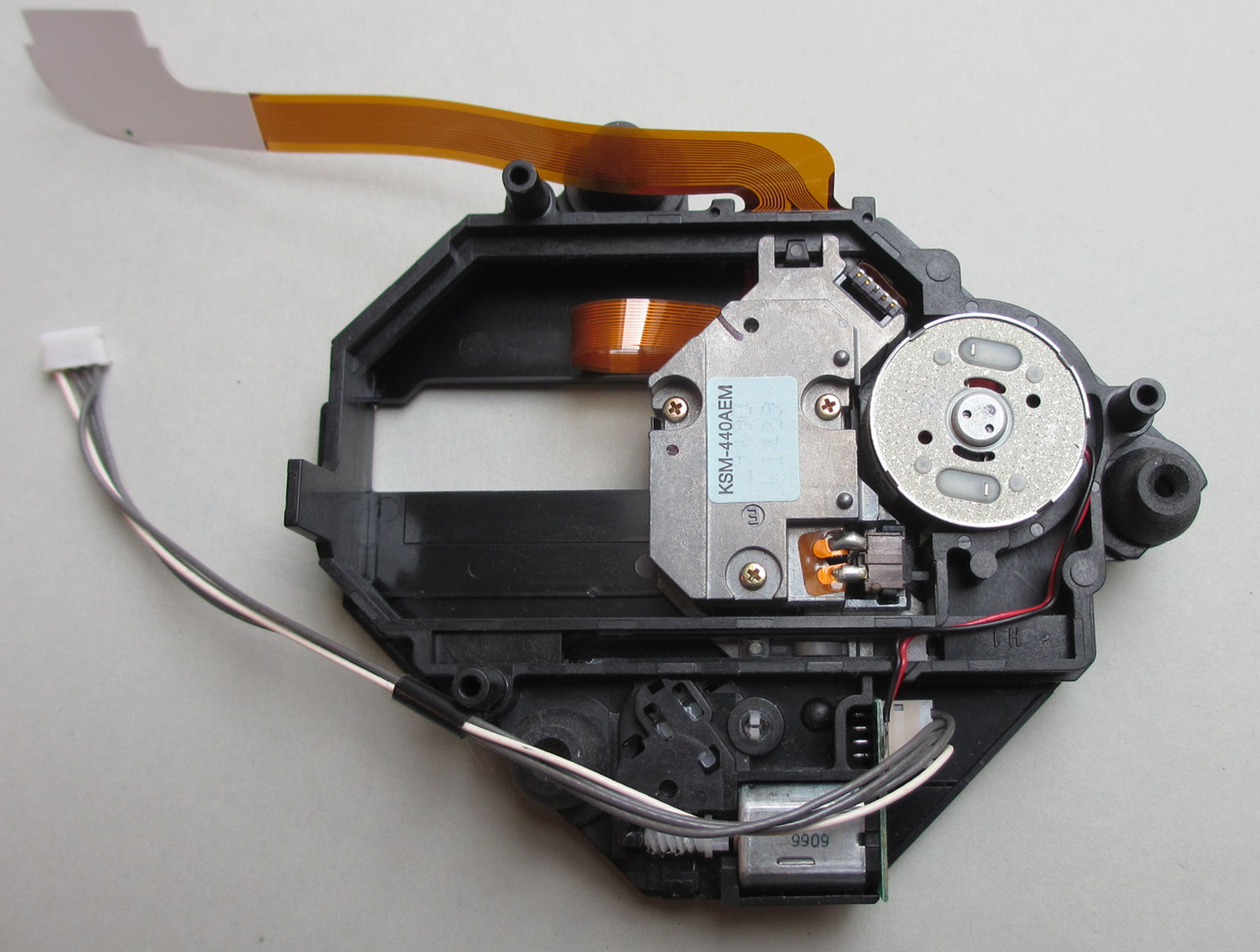
The cover has already been removed. The cover of the ACM drive will be put on later.
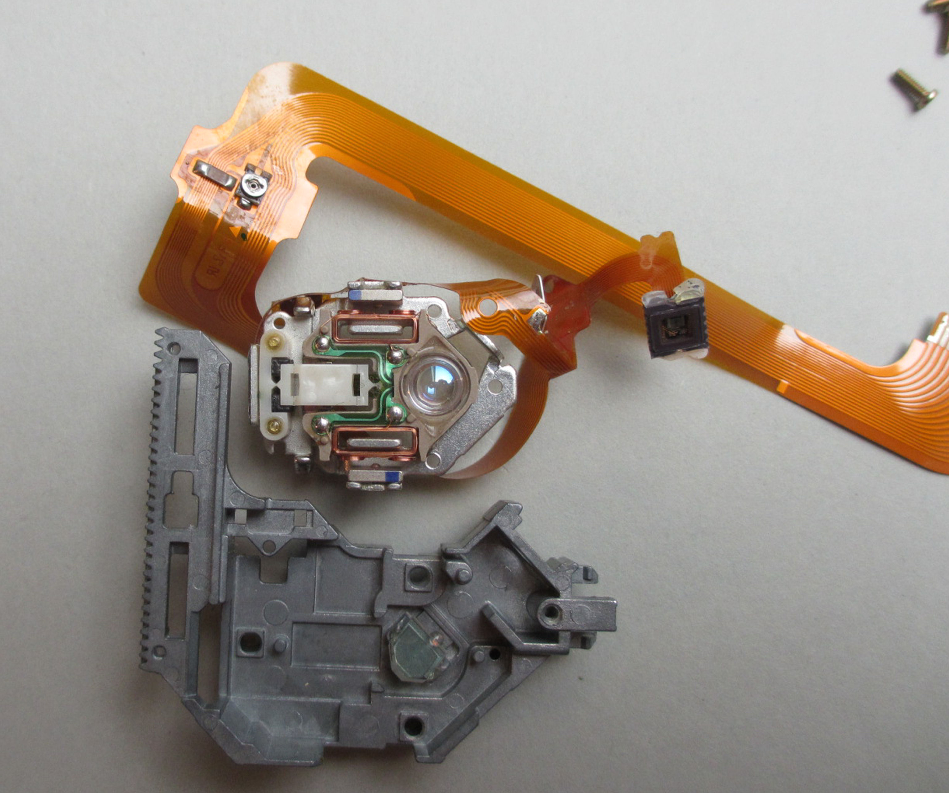
The limit switch is desoldered, taken out and put aside.
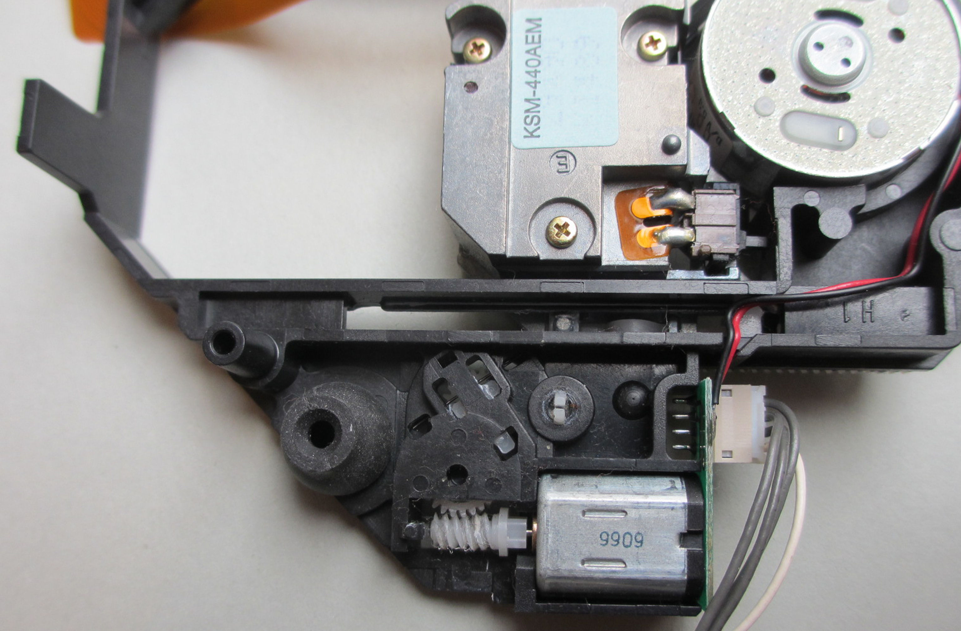
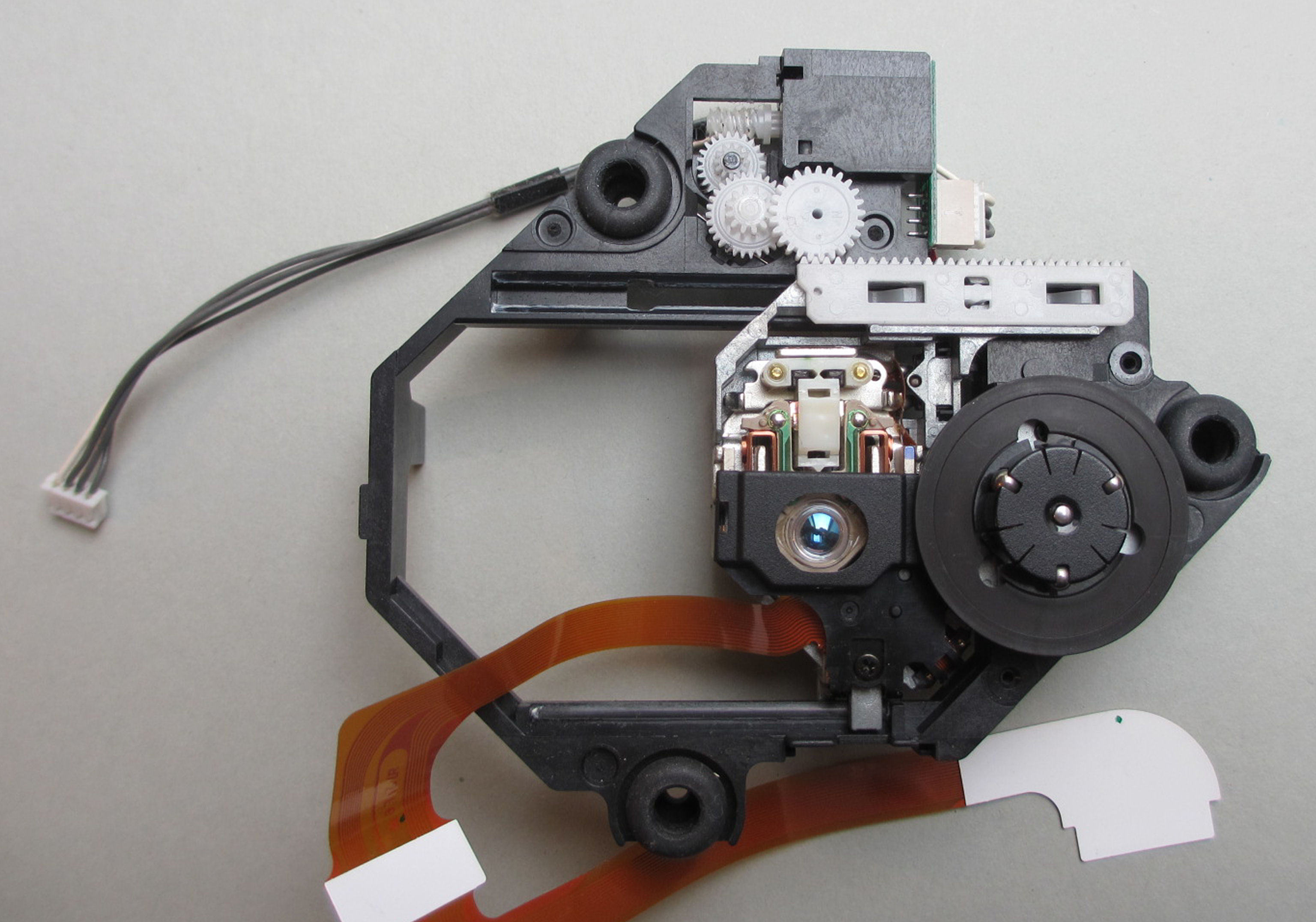
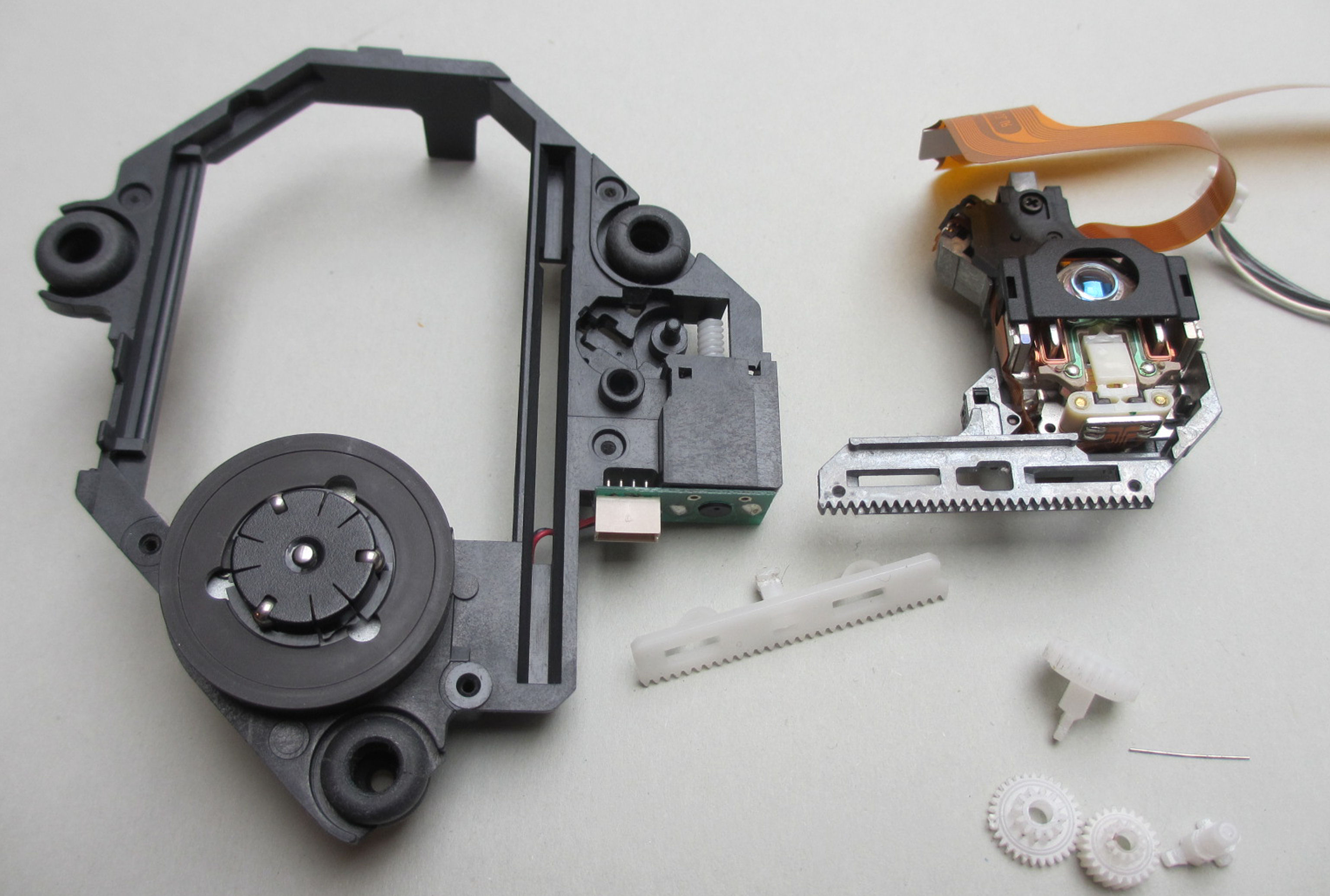
As you can see, two transmission parts have been removed. The laser slide can now be removed without any problems.
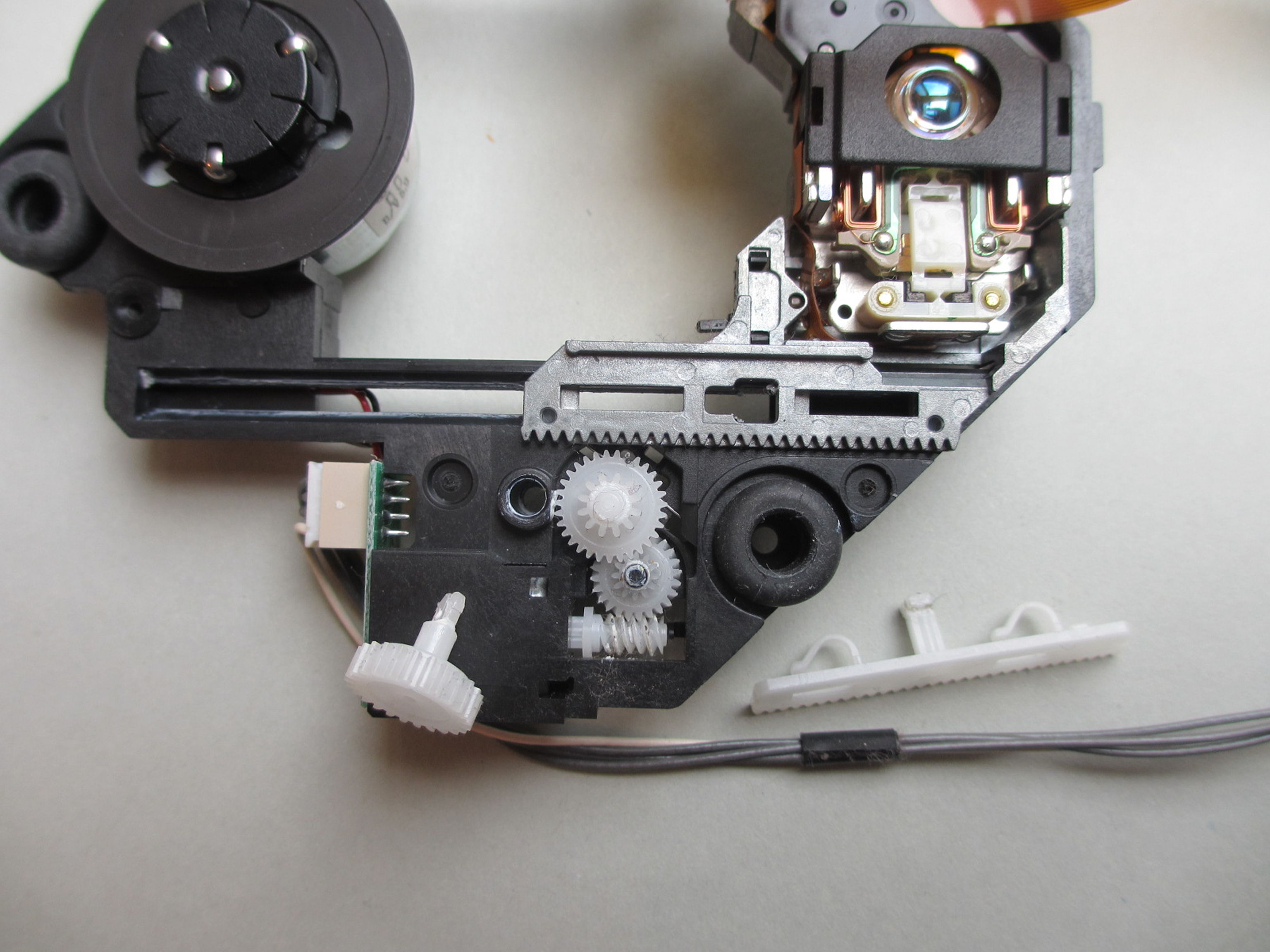
The laser sled is now next to it.
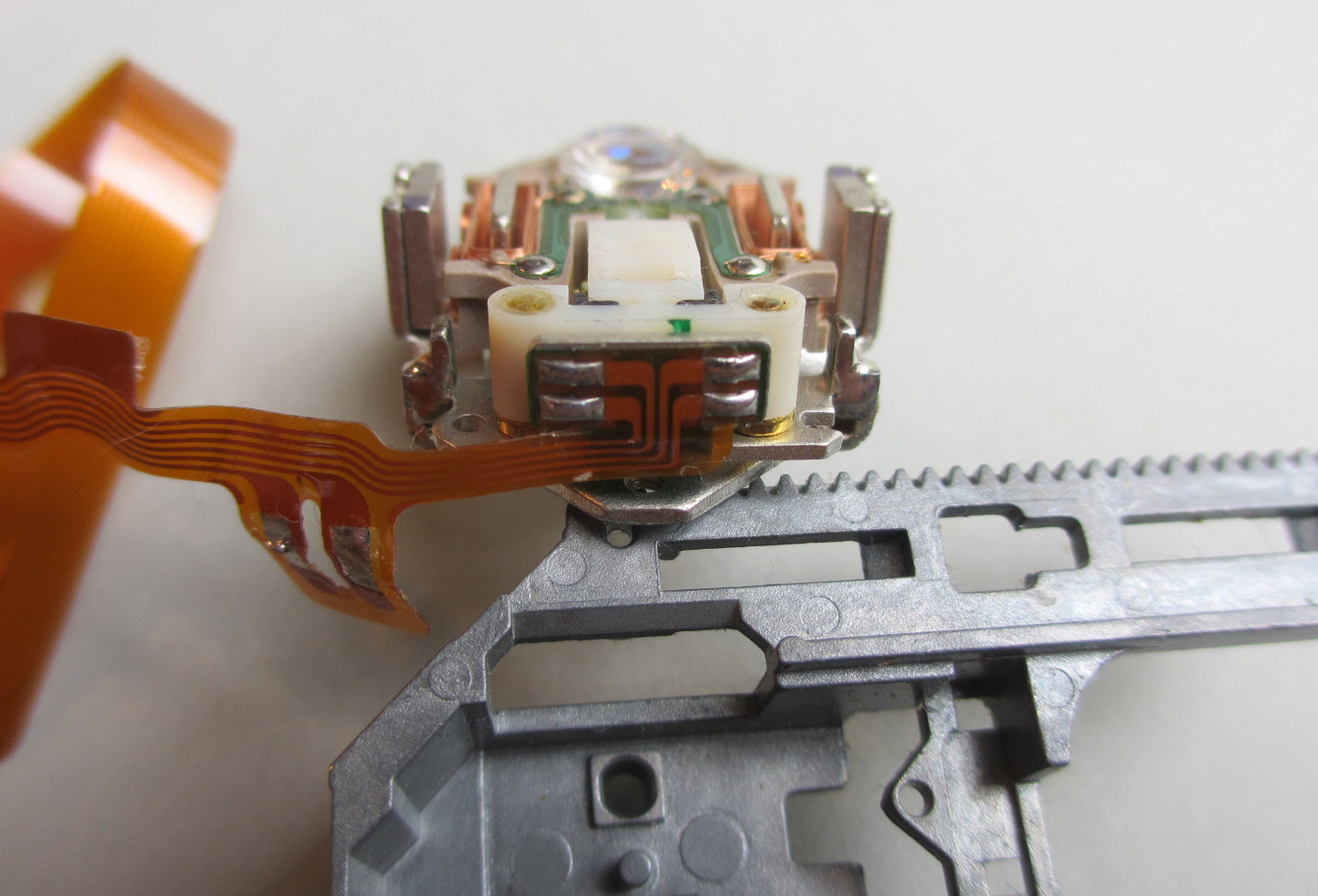
Checking the running surfaces is very important.
If the running surfaces have no abrasions or other damage, as in this case, the conditions for a reconstruction are already met.
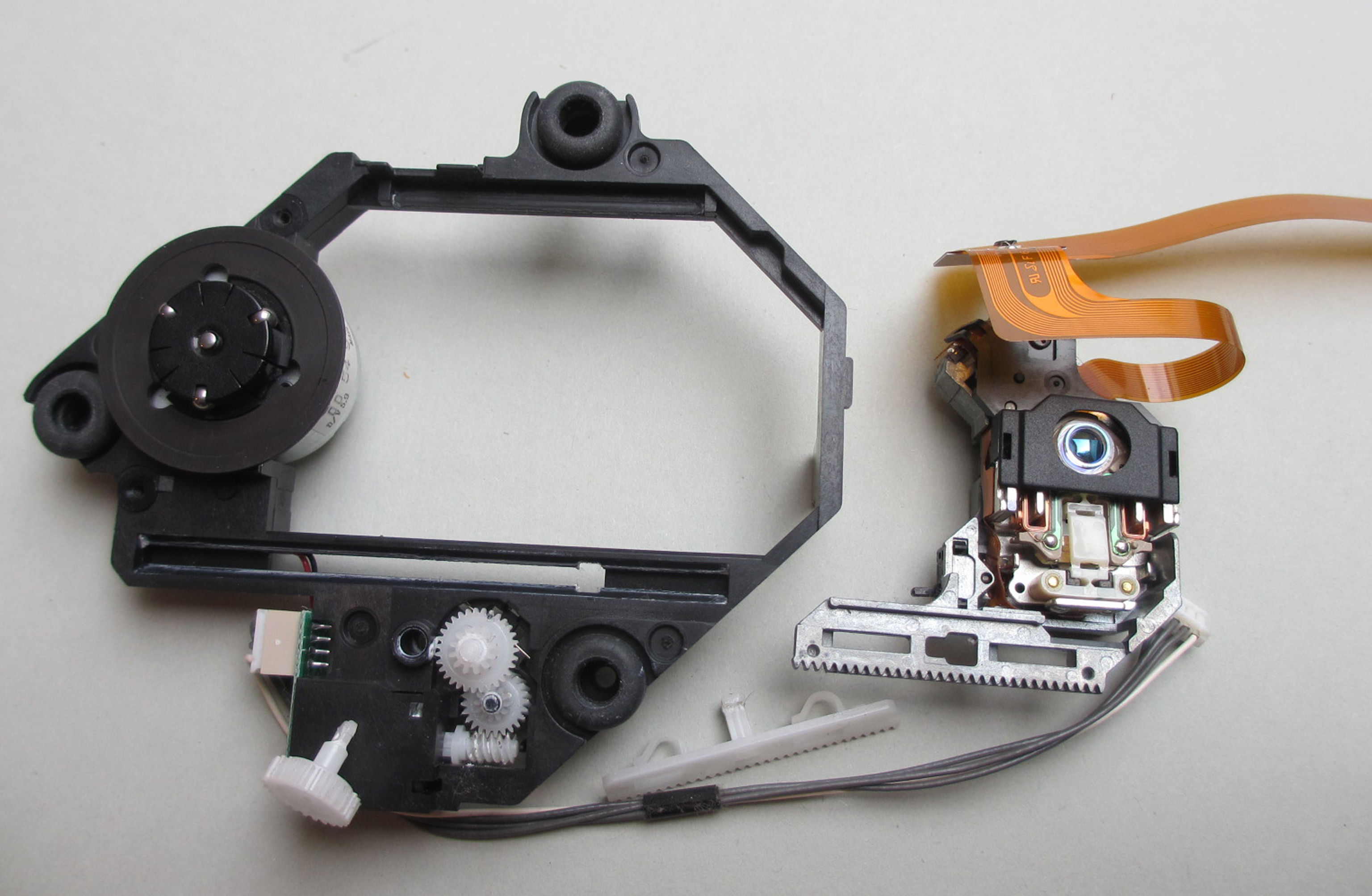
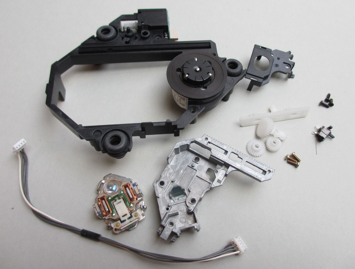
Everything is disassembled here.
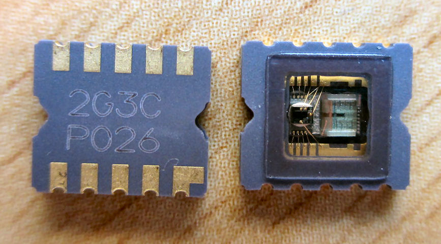
Now simply desolder and remove the limit switch. The laser chip is simply levered out.
This is how it should look then.
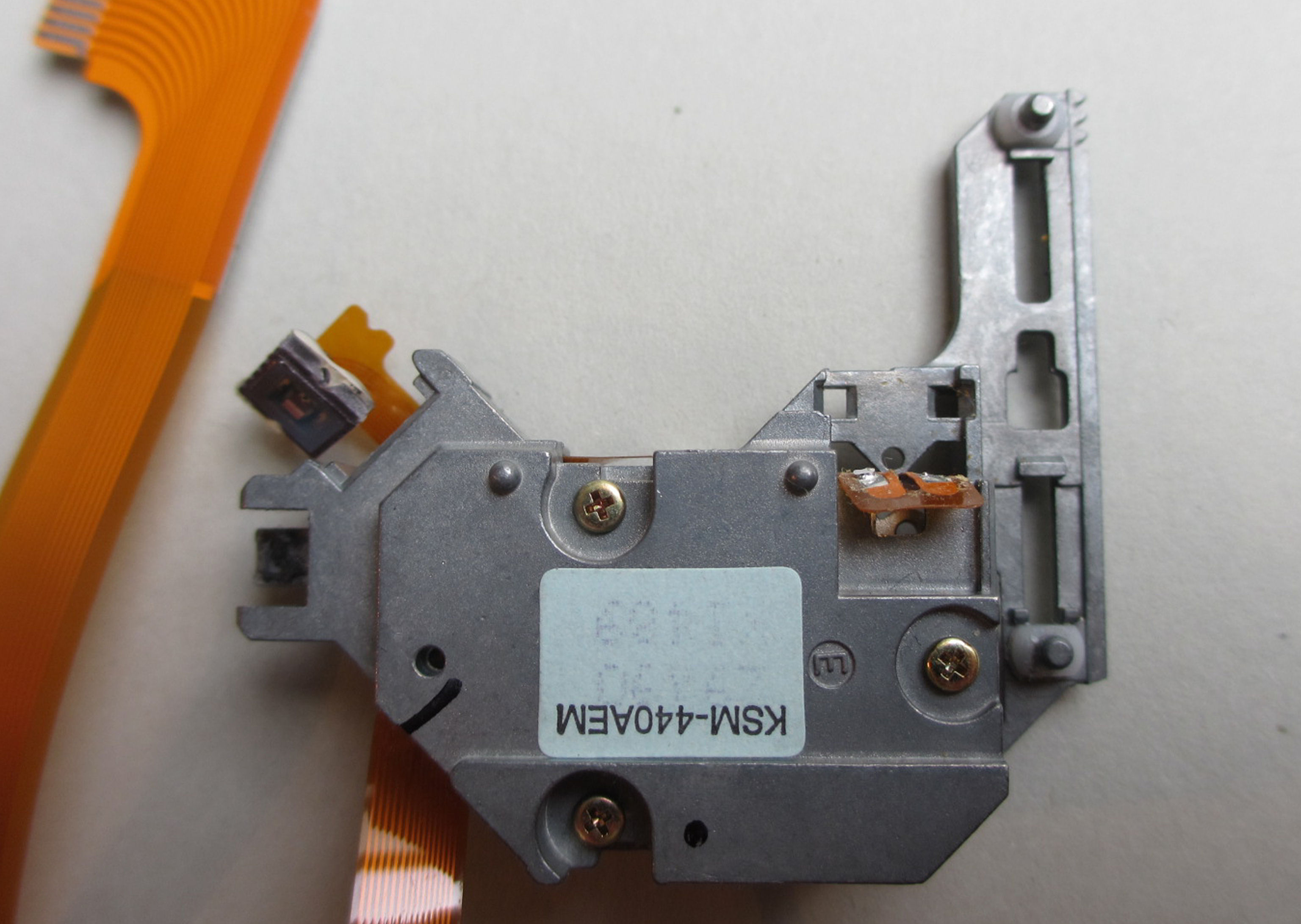
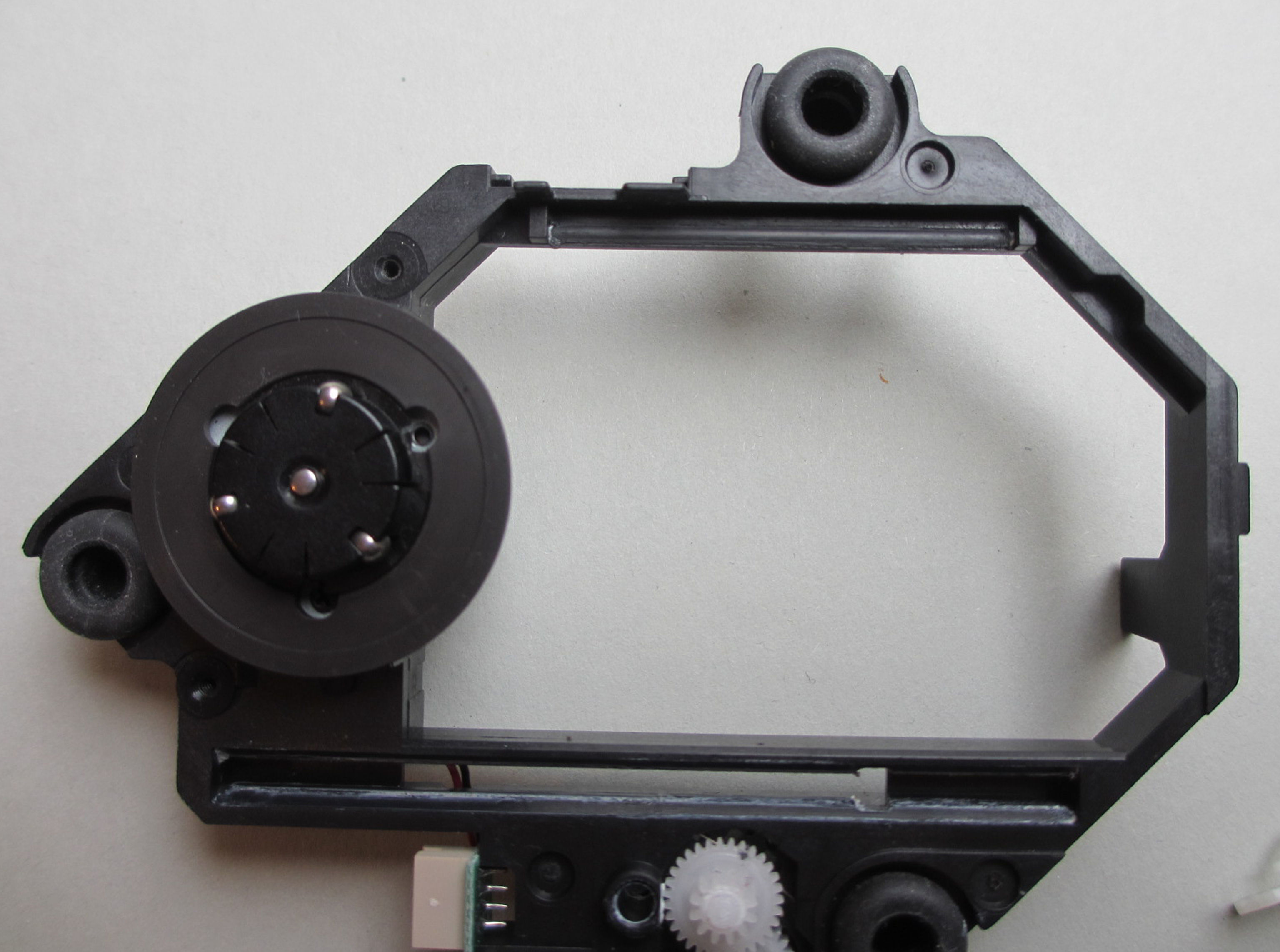
The flexible circuit board is partly glued to the case, but can be easily detached. Just don't use violence.
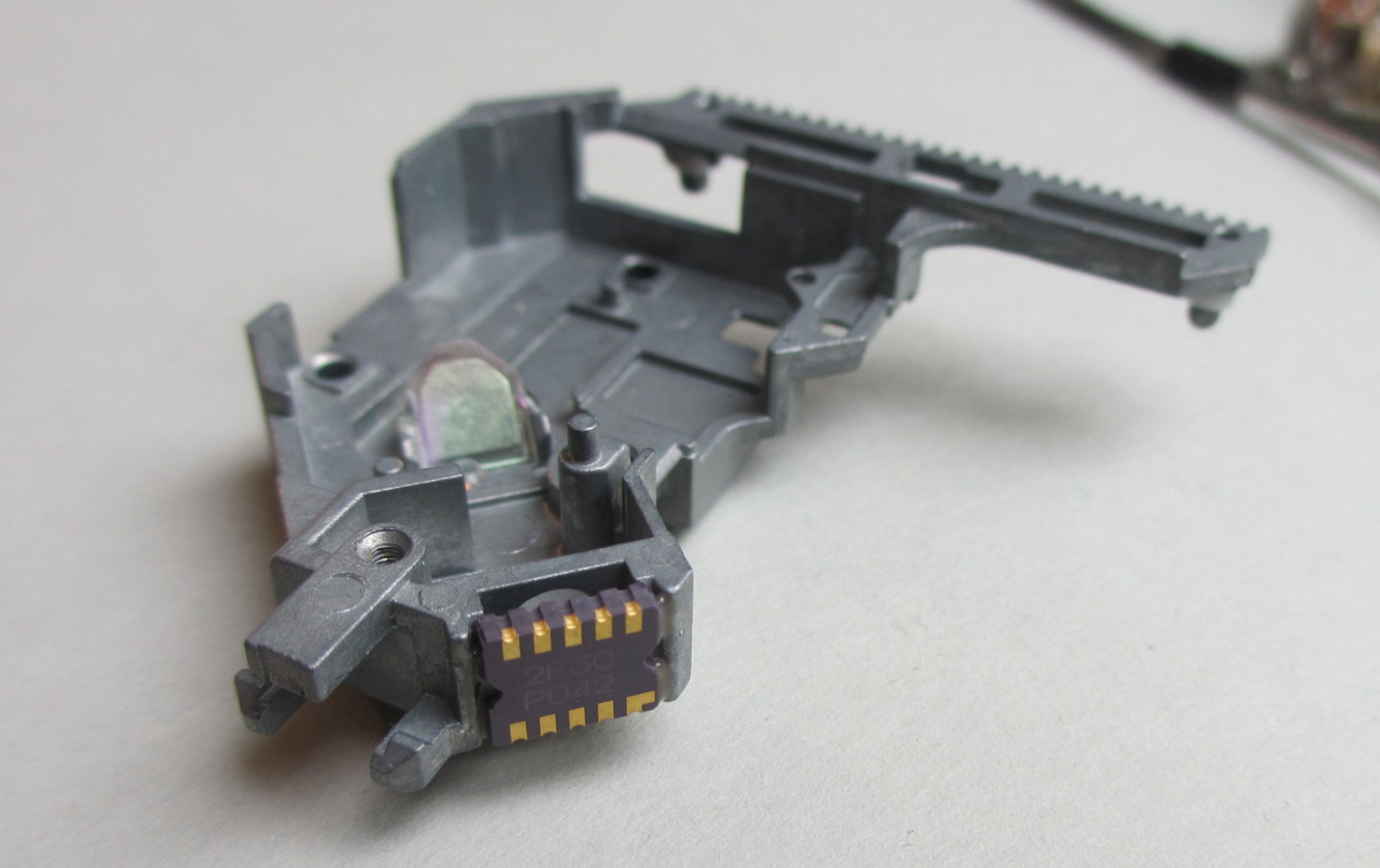
After the three screws on the back have been removed, the coil mechanism and flex circuit board can be removed. But everything very carefully.
Only remove the four solder joints cleanly.
Only what can be seen here will continue to be used. As you can see, only the flex board with the laser cell is missing.
This flexible circuit board was taken from an old ACM drive. The drive was junk, but the circuit board is perfectly suited to start a new life in an original Sony drive.
First, however, a brand new laser chip is used. It must be placed exactly the same as the previous one. The drive should do its job perfectly right away and bring us many hours of analog sounds.
And this is what the good bit looks like.
And, already deployed
But that's quick, the flex circuit board is already soldered on.
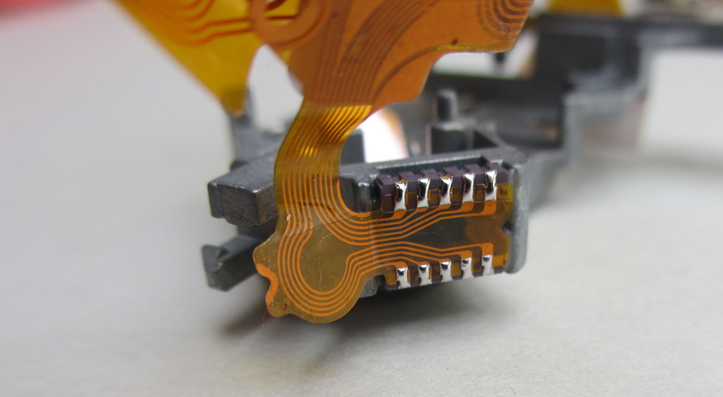
Oh, everything is fine here too.
So, now build the finished unit back into the housing.
Almost done, just put the cover from the old ACM laser unit on it.
FINISHED an original Sony KSM-440ACM REMAKE. It doesn't get more original. Oh yes, the three spacer tubes next to the rubber buffers still have to be removed, as well as the tab to the left of the laser carriage. See also next photo.
Very fussy users can lighten the die-cast slide by adding some material in order to reduce abrasion. Simply grind the aluminum housing flat before assembly.
The result, if you do everything right, is impressive. Full function right away. Well, 1.5 hours of fiddling shouldn't be for nothing.
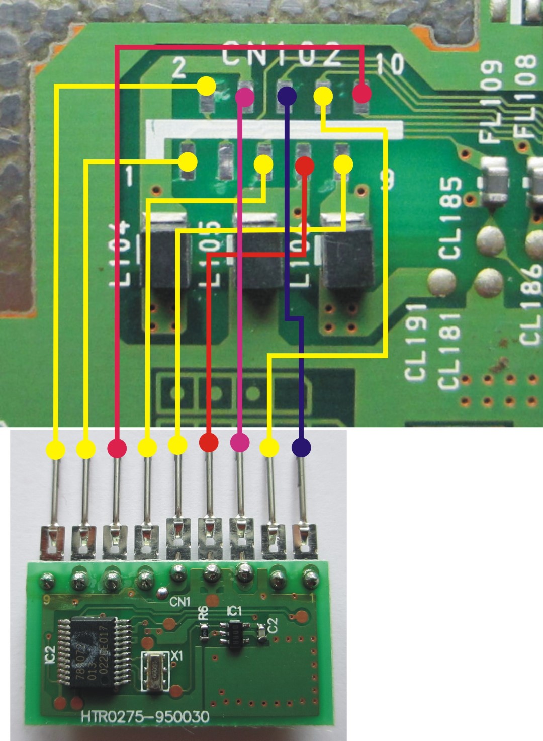
Remote controller
Your high-end Playstation should be equipped with a remote control?
Then simply follow these instructions and you can give commands to your device.
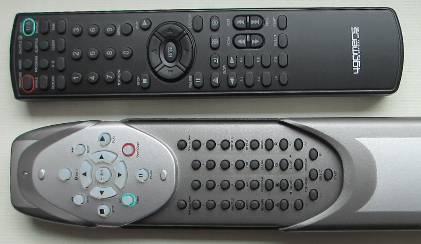
For this you need a DVD remote control for the Playstation 2 incl. IR receiver.
It does not necessarily have to be a SONY FB. Other remote controls can also be used. For example these two from 4gamers . The advantage is that the receivers of these two transmitters are compatible with the SONY FB and even confirm each keystroke with a flashing signal using a red LED.
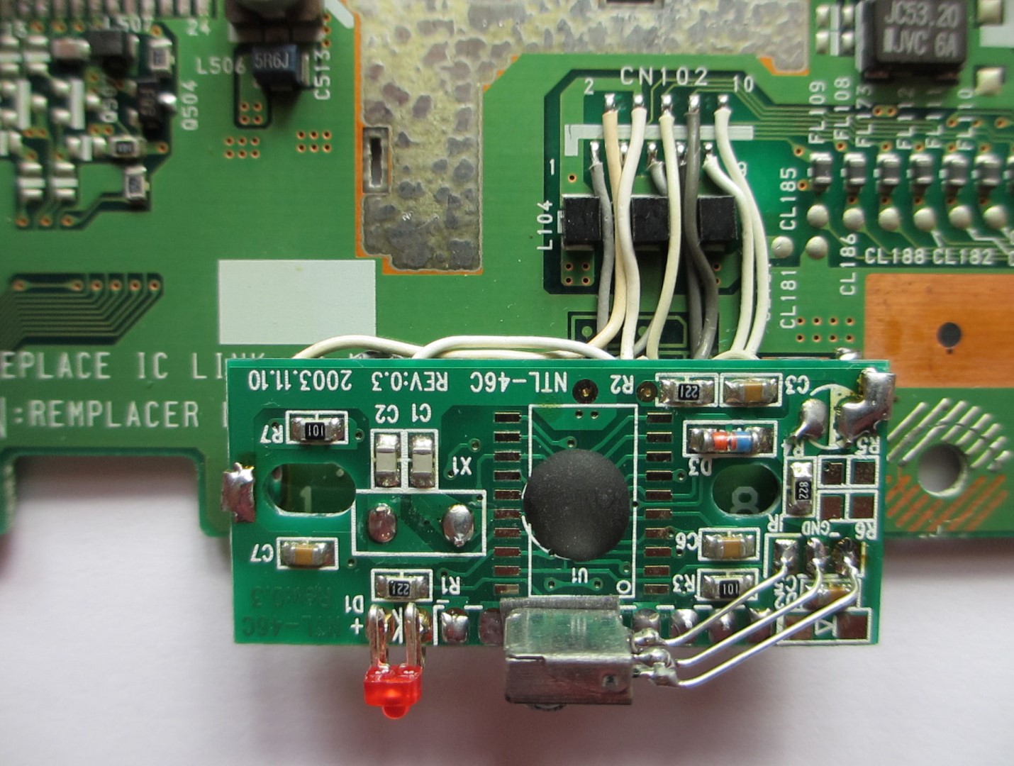
No special skills are required to implement the IR receiver in the port.
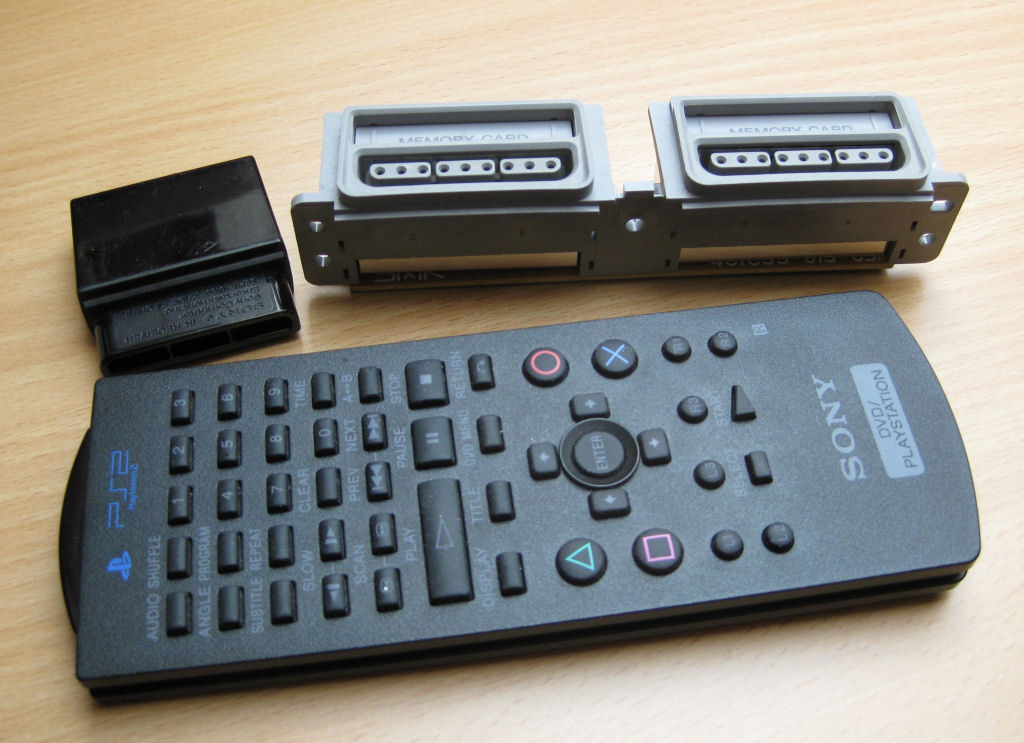
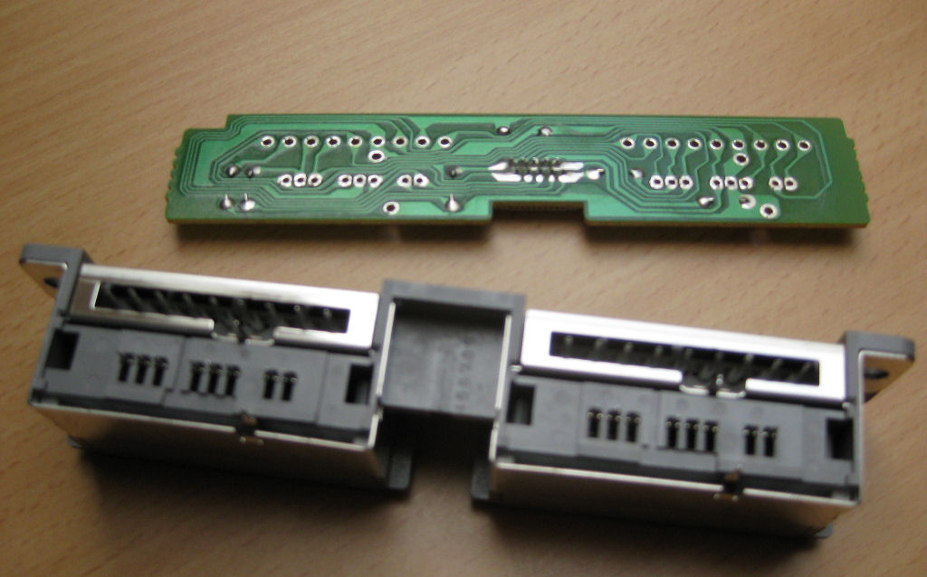
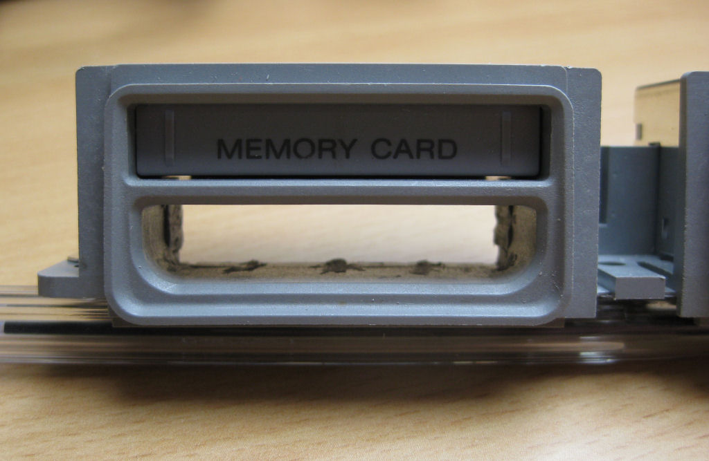
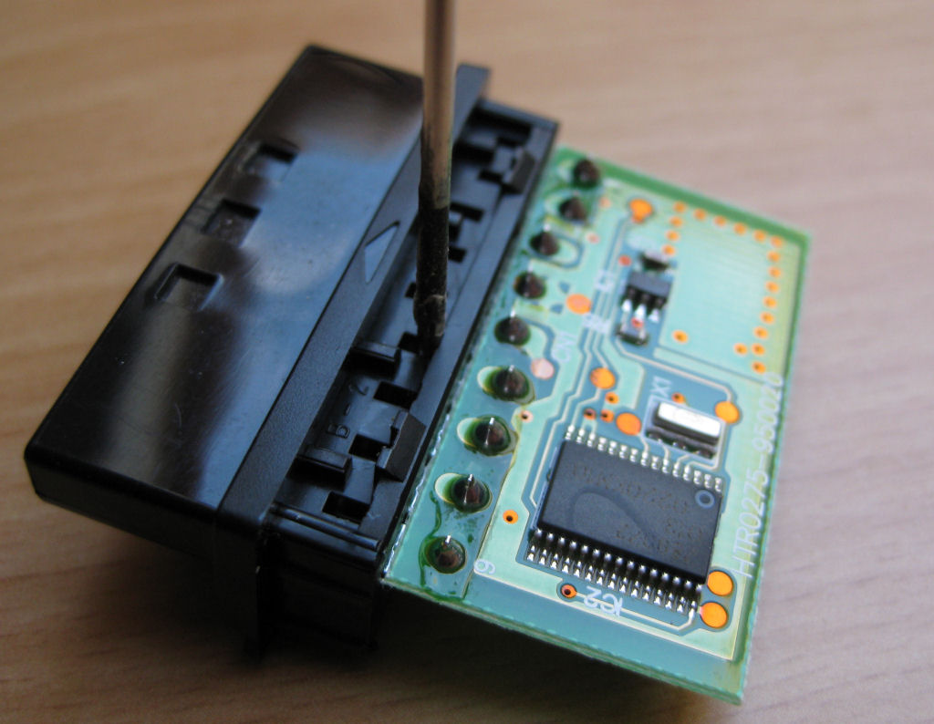
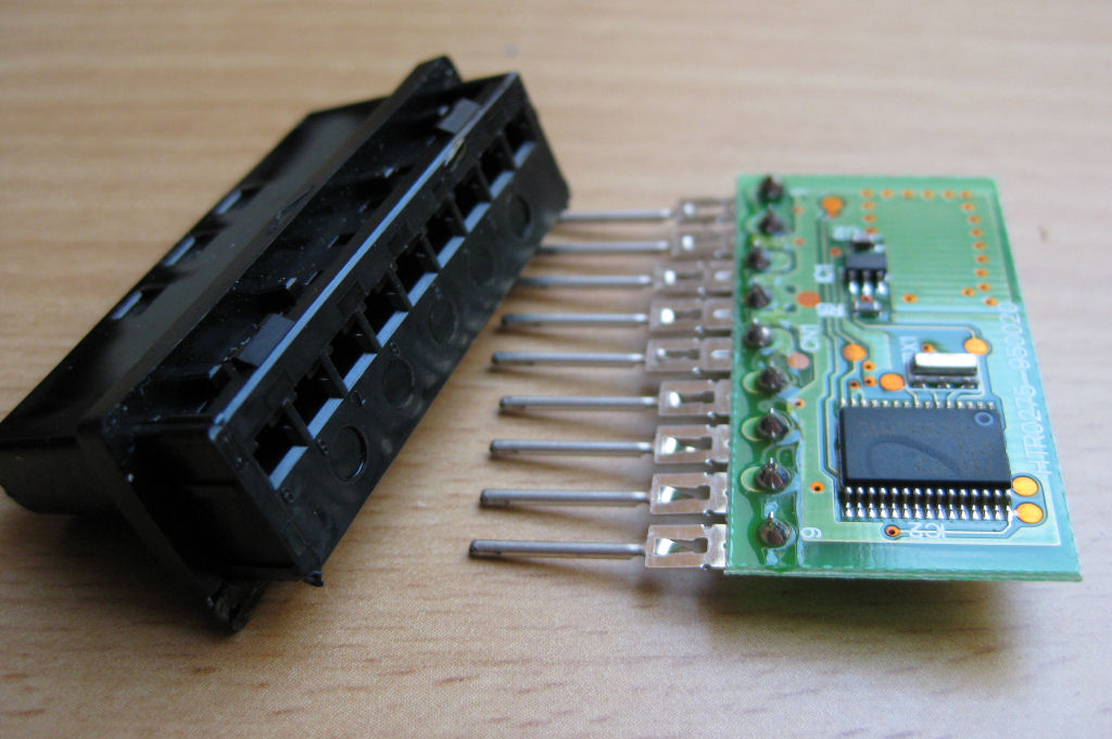
Here simply remove the circuit board from the port.
Simply pull out the parts shown from the left port. It's easy to do with a small pair of pliers.
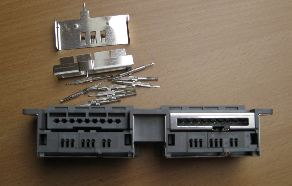
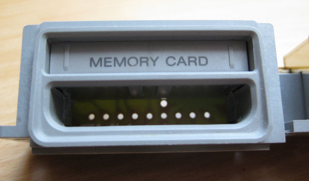
Clean out the shaft. I do it with a Dremel, super easy.
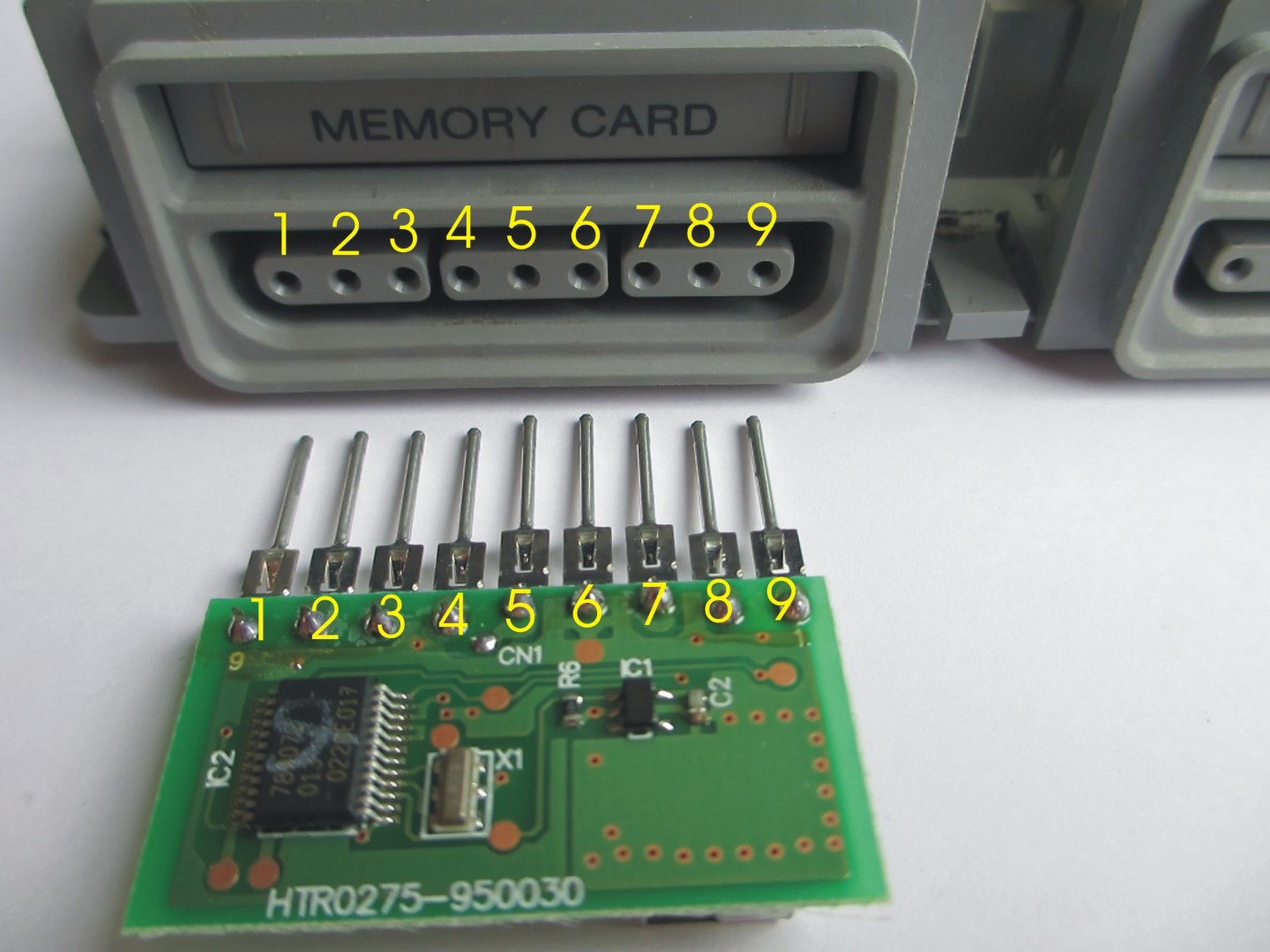
Put the previously removed circuit board back where it was and solder it.
Free the IR receiver from its housing.
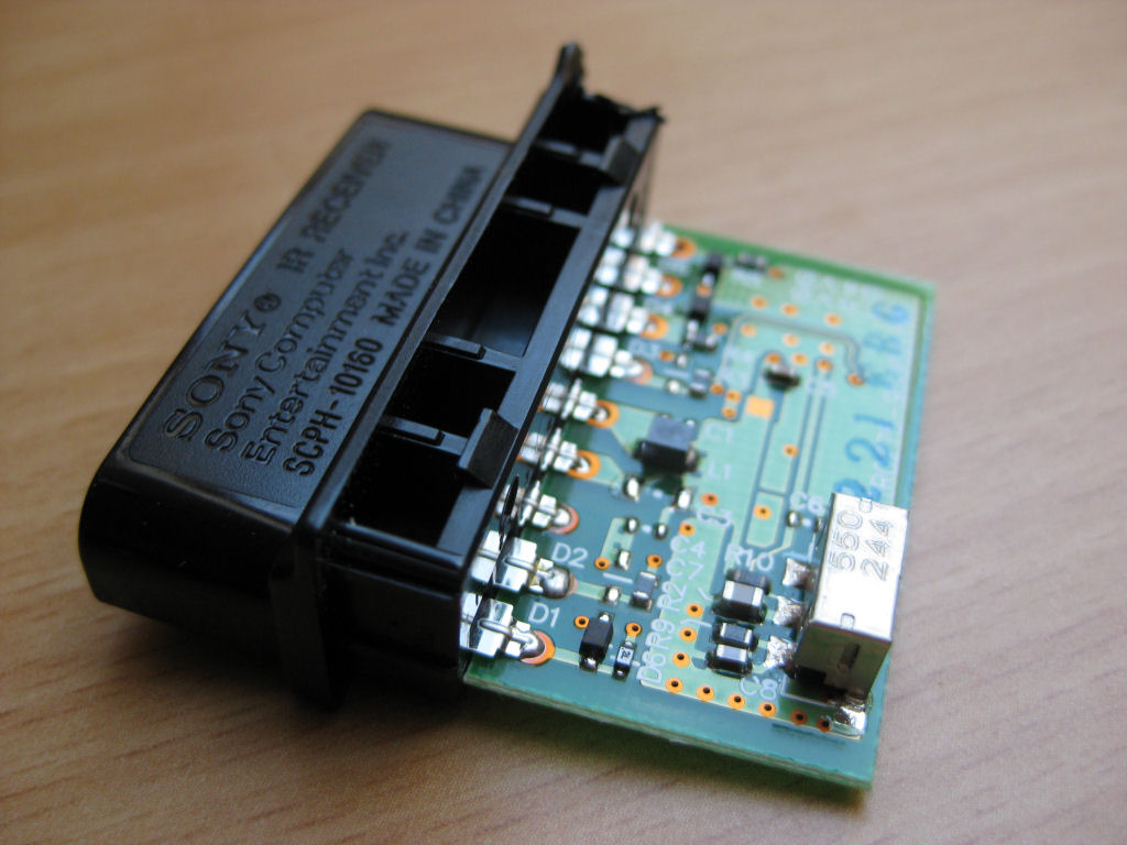
Then carefully press in the small tongues with a pointed object, a small screwdriver or a nail. Then the circuit board should be easy to remove.
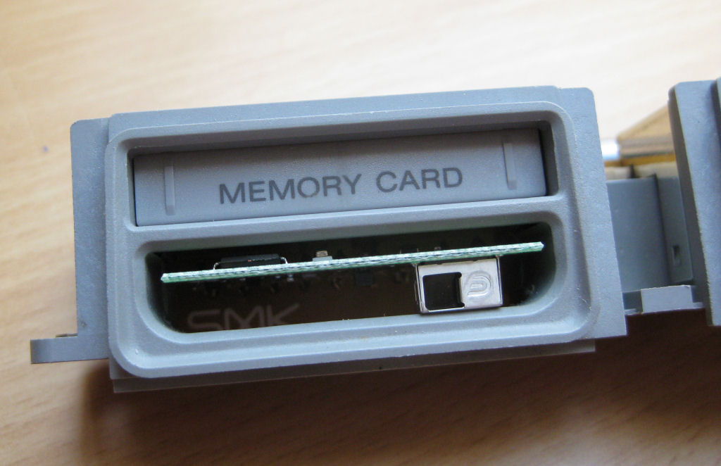
The whole thing looks like this
Then place the IR receiver in the port exactly as shown and solder it.
Anyone who uses the circuit board the wrong way round will be penalized with zero function.
FINISHED!
Or so....
Completely without a slot, the receiver is connected directly to the board and placed behind the panel. In my opinion the more elegant solution. In this way, any IR receiver can be easily integrated .
This is what it looks like with a 4gamers IR receiver.